89
ENG
pRack +0300025EN rel. 1.3 - 17.12.2015
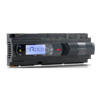
control the CO
2
condenser using the fans or the new EVS system:
Note: carefully check the pressure control settings; for general
uniformity of the software, automatic set point selection is not featured
for the diff erent types of control and diff erent types of refrigerant. For
example, the suggested default set point for the low temperature
compressors is 3.5 bars; in a cascade system (subcritical CO
2
) with R744
natural refrigerant, the reference pressure values are around 11 bars.
Together with the set point, the probe limits and probe alarm thresholds
will be correctly confi gured.
• Cascade, 2 suction lines, 2 condenser lines (external driver for managing
the heat exchanger on the second line), single board;
I/O
S2
S1
EVD
evolution
EEV
S3
FBUS
I/O
I/O
pR300
Fig. A.m
• Cascade, 2 suction lines, 2 condenser lines (built-in driver for managing
the heat exchanger on the second line), single board;
I/O
I/O
I/O
EEV
pR300
Fig. A.n
• Cascade, 2 suction lines, 2 condenser lines (built-in driver for managing
the heat exchanger on the second line), double board;
I/O I/O
I/O
S2
S1
EVD
evolution
EEV
S3
FBUS
pLAN
C1
NO1
NO2
NO3
C1
C4
NO4
NO5
NO6
C4
C7
NO7
C7
NO8
C8
NC8
G
G0
U1
U2
U3
GND
+VDC
+Vterm
GND
+5 VREF
U4
GND
U5
GND
VG
VG0
Y1
Y2
Y3
Y4
ID1
ID2
ID3
ID4
ID5
ID6
ID7
ID8
IDC1
J1 J24 J2 J3
J4 J5
J14
J10
J13J12
J15
FieldBus card BMS card
J11 pLAN
J25
BMS2
J26
FBus2
43 21
pR300
C1
NO1
NO2
NO3
C1
C4
NO4
NO5
NO6
C4
C7
NO7
C7
NO8
C8
NC8
G
G0
U1
U2
U3
GND
+VDC
+Vterm
GND
+5 VREF
U4
GND
U5
GND
VG
VG0
Y1
Y2
Y3
Y4
ID1
ID2
ID3
ID4
ID5
ID6
ID7
ID8
IDC1
J1
J24 J2 J3
J4 J5
J14
J10
J13J12
J15
FieldBus card BMS card
J11 pLAN
J25
BMS2
J26
FBus2
43 21
pR300
Fig. A.o
• Cascade, 2 suction lines, 2 condenser lines (built-in driver for managing
the heat exchanger on the second line), double board;
I/O I/O
I/O
EEV
pLAN
C1
NO1
NO2
NO3
C1
C4
NO4
NO5
NO6
C4
C7
NO7
C7
NO8
C8
NC8
G
G0
U1
U2
U3
GND
+VDC
+Vterm
GND
+5 VREF
U4
GND
U5
GND
VG
VG0
Y1
Y2
Y3
Y4
ID1
ID2
ID3
ID4
ID5
ID6
ID7
ID8
IDC1
J1
J24 J2 J3
J4 J5
J14
J10
J13J12
J15
FieldBus card BMS card
J11 pLAN
J25
BMS2
J26
FBus2
43 21
pR300
pR300
Fig. A.p
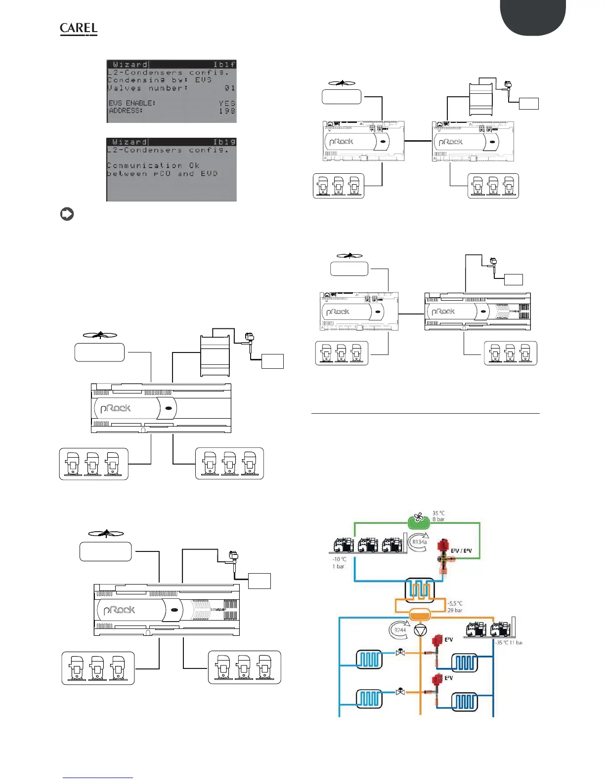
A2.2 Pumped
Less used than traditional cascade subcritical systems, this solution
limits the use of HFC refrigerants to the equipment rooms. The medium
temperature units are supplied with pumped liquid CO
2
, while the low
temperature units are fi tted with expansion valves. The CO
2
is cooled
by a dedicated chiller (NH3 or r134a) inside a tank, normally with a tube
bundle evaporator. In addition to traditional systems, these also include
management of the pumps that deliver the liquid CO
2
to the medium
temperature evaporators, where it does not expand but rather is only
superheated and returns to the receiver in a semi-liquid state.
Fig. A.q
Board with
pLAN address 1
Board with
pLAN address 1
Board with
pLAN address 1
Board
with
pLAN
address 2
Board with
pLAN address 1
Board with
pLAN
address 2
 Loading...