42
ENG
pRack +0300025EN rel. 1.3 - 17.12.2015
Fan for medium temperature line
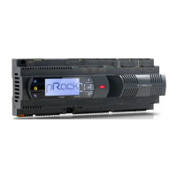
The following parameters need to be set to manage the fan:
• Condensing pressure threshold (default 16 bars)
• Shutdown evaluation time with pressure higher than threshold(default 180 s)
• Shutdown evaluation time with pressure lower than threshold(default 60 s)
• Shutdown delay (default 20 s)
The following table highlights the cases in which the fan is activated with
reference to the default values:
Condensing
pressure (Pcond)
CRII % activation (*) Fan
Pcond >= 16bar 50% o 0% Switch on
Pcond < 16bar 50% o 0% Keep off or switch off after 0s + 20s
Pcond >= 16bar 0% Keep on
Pcond < 16bar 0% Keep off or switch off after 60 s + 20s
Pcond >= 16bar 50% Keep off or switch off after 180 s + 20 s
Pcond < 16bar 50% Keep off or switch off after 60 s + 20 s
Fan for low temperature line
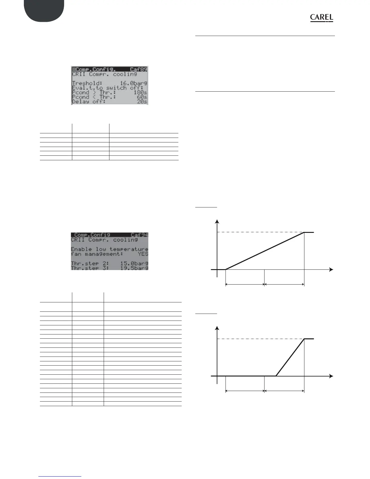
The following parameters need to be set to manage the fan:
• Condensing pressure threshold P1 (default 7.5 bars) didepending on
the capacity step
• Condensing pressure threshold P2 (default 15 bars) didepending on
the capacity step
• Condensing pressure threshold P3 (default 19.5 bars) didepending on
the capacity step
• Shutdown evaluation time with pressure higher than threshold(default 180 s)
• Shutdown evaluation time with pressure lower than threshold(default 60 s)
• Shutdown delay (default 20 s)
The following table highlights the cases in which the fan is activated with
reference to the default values, with 3 capacity steps:
Condensing
pressure (Pcond)
CRII % activation
(*)
Fan activation
Pcond<P1 (condi-
tion not allowed)
OFF Keep off or switch off after 0s + 20s
P1<=Pcond<P2 step1 o 0% Switch on
P2<=Pcond<P3 step1 o0% Switch on
Pcond>=P3 step1 o 0% Switch on
P1<=Pcond<P2 0% Keep on
P2<=Pcond<P3 0% Keep on
Pcond>=P3 0% Keep on
P1<=Pcond<P2 step2 o step1 Keep off or check step1 switch off condition
P2<=Pcond<P3 step2 o step1 Switch on
Pcond>=P3 step2 o step1 Switch on
P1<=Pcond<P2 step1 Keep off or switch off after 60 s + 20s
P2<=Pcond<P3 step1 Switch on
Pcond>=P3 step1 Switch on
P1<=Pcond<P2 Step3 o step2 Keep off or check step2 switch off condition
P2<=Pcond<P3 Step3 o step2 Keep off or check step2 switch off condition
Pcond>=P3 Step3 o step2 Switch on
P1<=Pcond<P2 step2 Keep off or switch off after 60 s + 20s
P2<=Pcond<P3 step2 Keep off or switch off after 180 s + 20s
Pcond>=P3 step2 Switch on
P1<=Pcond<P2 step3 Keep off or switch off after 60 s + 20s
P2<=Pcond<P3 step3 Keep off or switch off after 180 s + 20s
Pcond>=P3 step3 Switch on
6.4 Fans
pRack pR300 can manage up to 2 condenser lines with up to 16 fans and
one speed modulation device each, applying common types of device
rotation and controlling both the starting mode and some accessory
functions. The modulation device may be an inverter or a phase fi red
controller. The fan functions and related parameter settings are enabled
from main menu branch D.a/D.b. The functions are described in detail
below.
6.4.1 Control
pRack pR300 can manage - as described in paragraph 6.2 - proportional
band and Neutral zone control, by pressure or temperature. For details on
the control modes, see the corresponding paragraph, while below is the
description only of the features relating to the fans.
Fan operation depending on the compressors
The operation of the fans can be bound to the operation of the
compressors by setting a parameter in main menu branch D.a.b/D.b.b, in
this case the fans only start if at least one compressor is on. This setting is
ignored if the fans are controlled by a dedicated pRack pR300 board and
the pLAN network is disconnected.
Fan operation with modulating device
If the fans are controlled by a modulating device, the meaning of the
parameters that associate the minimum and maximum values of the
device’s modulating output and the minimum and maximum capacity of
the modulating device on screens Dag02 and Dbg02 is illustrated in the
following examples.
Example 1: minimum modulating output value 0 V, maximum value 10 V,
minimum modulating device capacity 0 %, maximum 100 %.
Max output
value = 10 V
Min output
value = 0 V
Regulation
probe value
Setpoint
Dierential
Analog output
Dierential
Min capacity = 0 %
Max capacity = 100 %
Fig. 6.s
Example 2: minimum modulating output value 0 V, maximum value 10 V,
minimum modulating device capacity 60 %, maximum 100 %.
Max output
value = 10 V
Min output
value = 0 V
Regulation
probe value
Setpoint
Dierential
Analog output
Dierential
Min capacity = 60 %
Max capacity = 100 %
Fig. 6.t
 Loading...