18
ENG
“UEX-PLUS” +0300040EN - rel. 1.4 - 25.09.2015
installeruserservice
5. REMOTE TERMINAL, GSM MODEM AND SUPERVISORY NETWORK
5.1 Remote display terminal
The display terminal can be detached from the humidifi er and moved to
another place.
Depending on the distance required, the following are necessary:
• up to 50 metres: 6-wire telephone cable and two EMC fi lters (code
0907858AXX) (see Fig. 5.a);
• up to 200 metres: two CAREL TCONN6J000 boards, 6-wire telephone
cables and an AWG20-22 shielded cable with 3 twisted pairs (for the
connection of the two boards, Fig. 5.b).
Note: to fi ll the empty space left by the display terminal on the
humidifi er, use CAREL kit code HCTREW0000.
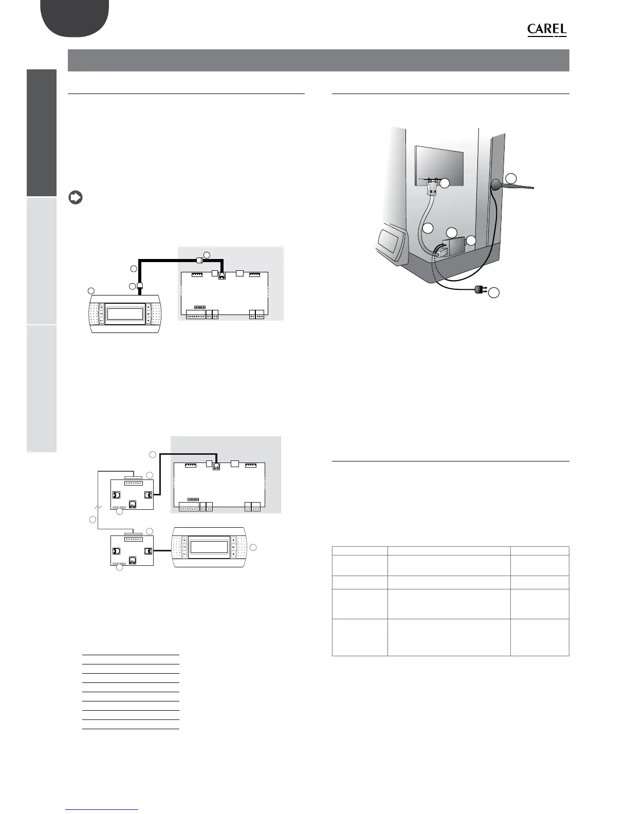
Remote connection of the terminal up to max 50 m
J18
humiSteam
3
2
1
2
Fig. 5.a
Key:
1 telephone cable (up to 50 m distance);
2
EMC fi lters (code 0907858AXX) to be applied to the ends of the
telephone cable;
3 remote display terminal.
Remote connection of the terminal up to 200 m
J18
humiSteam
4
2
2
A
J14
1 2 31 2 3
J15
B
C
SC
A
J14
1 2 31 2 3
J15
B
C
SC
5
3
3
1
Fig. 5.b
Key:
1 telephone cable (up to 0.8 m distance);
2 CAREL TCONN6J000 board;
3 pin strip J14 and J15 in position 1-2 (power supply available on the
telephone connectors A, B and C and screw SC);
4
WG20-22 shielded cable with 3 twisted pairs to move the display
terminal up to 200 m away. Connection to the TCONN6J00 board:
terminal SC function
0 EARTH (shield)
1 +VRL
2 GND
3 RX/TX-
4 RX/TX+
5 GND
6 +VRL
5 remote display terminal
5.2 GSM network connection (send SMS)
The humidifi er can be confi gured to send SMS message for alarms and
malfunctions (see menu installer > supervisor > GSM protocol).
humiSteam
J19
1
2c
3
MODEM
2a
2d
2b
Fig. 5.c (inside humidi er, electrical compartment)
Key:
1 electronic board PCOI00MDM0 (to be connected to connector J19 on
the humidifi er board)
2
• CAREL GSM kit PLW0PGSM00, made up of:
• 2.a modem
• 2.b antenna (with magnetic base)
• 2.c serial cable
• 2.d power supply
3 SIM card to be inserted in the modem. Make sure that the access
password (PIN number) is not enabled
5.3 Supervisory network (J19)
The humidifi er is equipped with serial interface:
• PCOS004850 (for connections protocol Carel, Modbus®, Winload)
Instead of the supplied, they can be connected to a supervisory system
via RS232 serial lines or FTT10 LON using the optional cards shown in the
following table.
optional cards characteristics supported protocols
PCO1000WB0 provides BACnet 8802.3 Ethernet,
BACnet/IP and MS/TP connectivity
BACnet™
PCO1000BA0 Provides BACnet MS/TP over RS485 BACnet™
PCO100MDM0 used for the direct interface of the
controller to an RS232 network with
an external modem
CAREL for
remote
connections
PCO10000F0 used to interface of the controller
to an FTT10 LON network, when
suitably programmed
LON-Echelon®
Tab. 5.a
Connection is also possible to TREND systems using a card sold directly
by TREND.

 Loading...