BT2 user manual - H-5911-9004-02-B Page | 112
To name the alignment, enter a name in the Alignment ID text field. By default the name is Alignment hh:mm.
The heading of the alignment jig can be entered in the Azimuth frame. Note that the different methods listed under
Azimuth are determined by the configuration of settings in the Settings window > Hole tab (see section 11.3.7).
Some methods may be disabled if they are considered redundant for your operations.
The available methods are listed below.
• Heading: If you have surveyed in the alignment jig and computed a heading, select the Heading radio
button and enter the surveyed value.
• Back Point: manually enter a ‘back point’ coordinate. A heading is computed from the back point to the
hole collar.
• Two Point: manually enter a back point and a front location. A heading is computed from the back point to
the front location.
• Relative: If you have lined up the alignment jig between two holes which have been defined in your project,
select the Relative radio button. Select two hole collars from a To and a From drop down list. A heading is
computed between the two locations.
• Use Existing: select a previously used alignment from a drop down list. The heading is copied from the
selected alignment.
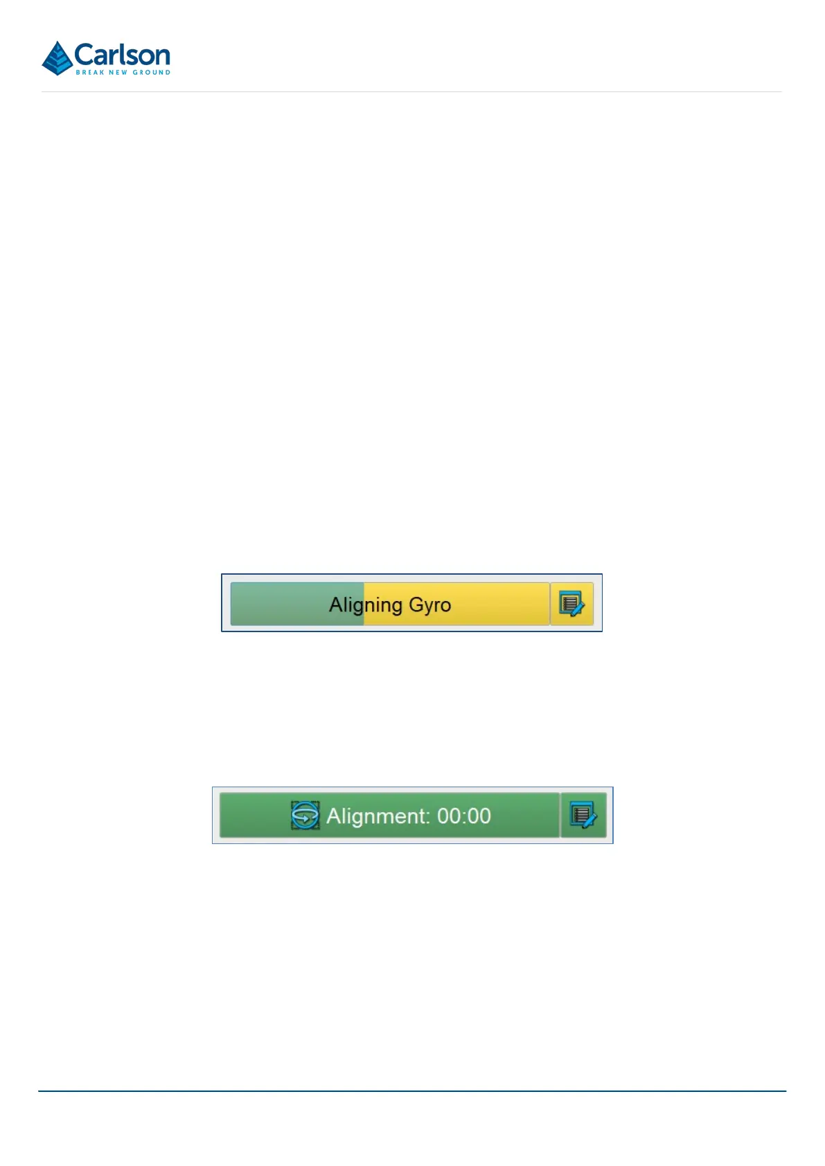
15.4.2 Aligning (yellow / green)
The gyro is currently aligning.
The Gyro button turns yellow and a green progress bar shows the progress of the alignment. If the probe moves
during the alignment then the progress of the alignment is reset.
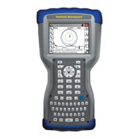
15.4.3 Live (green)
The gyro is aligned and functional.
After this stage, the Align Gyro button disappears and is replaced by the Alignment icon at the top of the Control
tab.
Note that if, during the survey, the probe is moved beyond the limitations of the gyro (i.e. a faster than the
960°/second maximum rotation rate) then an error message appears. The Alignment icon turns red and the gyro
must be realigned on the alignment jig.
Figure 123 Gyro - aligning
Figure 124 Gyro - aligned