145
6.4 — Smart Controller Configuration
The smart controller’s configuration switch is a manual
switch the operator must configure before powering up the
unit. The configuration DIP switch has 4 positions (A, B, C,
D) and corresponds to the type of compressor and compres-
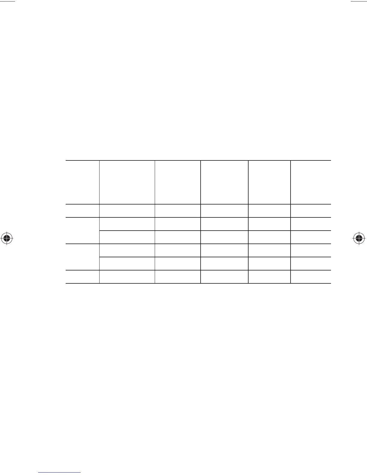
sor modulation range. The table below and Fig. 34 and 35
show the DIP switch positions to correctly configure the
smart controller to the smart compressor. The configuration
switch can be positioned at any time while the smart con-
troller is off.
Configu-
ration
DIP
Switch
Position
Compressor
Models
# of
Compres-
sor
Cylinders
# of
Unloaders
on
Compressor
Modula-
tion Range
Electrical
Schematic
A 06D, 06E 6 2 33% - 100% Figure 36
B 06D, 06E 6 2 67% - 100% Figure 36
06M 3 1 67% - 100% Figure 37
C 06D, 06E 4 1 50% - 100% Figure 37
06D, 06CC, 06M 3, 4, or 6 PWM Valve 20% - 100% Figure 37
D All 3, 4, or 6 None None NA