50
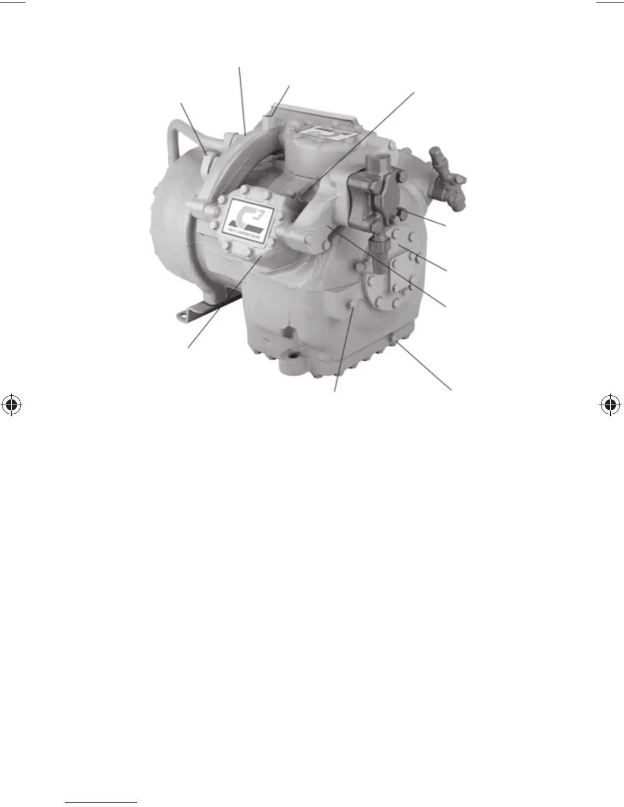
CONNECTION FROM
SUBCOOLING HEAT
EXCHANGER, SEE FIG. 14B
FOR PORT TO
DESUPERHEAT LOW
STAGE DISCHARGE
INTERSTAGE
MANIFOLD
1/2-13 UNC-LIFTING LUG
CONNECTION (LUG NOT
SUPPLIED WITH
COMPRESSOR)
1/4-NPT INTERSTAGE
PRESSURE TAP*
(INCLUDES SCHRADER
FITTING TO RELIEVE
CRANKCASE PRESSURE)
SUCTION VALVE
LOCATION (TO LOW
STAGE CYLINDERS)
1/4" NPT HIGH SIDE
OIL SAFETY SWITCH
CONNECTION
SUCTION MANIFOLD
(TO LOW STAGE
CYLINDERS)
7/16"-20 SAE OIL
DRAIN CONNECTION
(WAS 1/4" NPT)
1/4-NPT LOW STAGE
PRESSURE TAP
(NOT SHOWN)
1/4" NPT OIL FILL (SUMP)
CONNECTION ALSO LOW
SIDE OIL SAFETY SWITCH
LOCATION
*BOTTOM OF CYLINDER
HEAD HAS A BOSS AND
1/4 NPT JUST LIKE THE TOP
NOTE: Bolt sizes and thread pitch: Compressors are built using English unit
bolts. The bolts have no exact metric equivalents. Therefore, to prevent possible
cross-threading, loose bolts, or damage to threaded portions of the casing,
comparable metric measurements are not included.
Fig. 14A — 06CC Compressor (16 to 37 Cfm), 06D Body Pump
End Connection Points