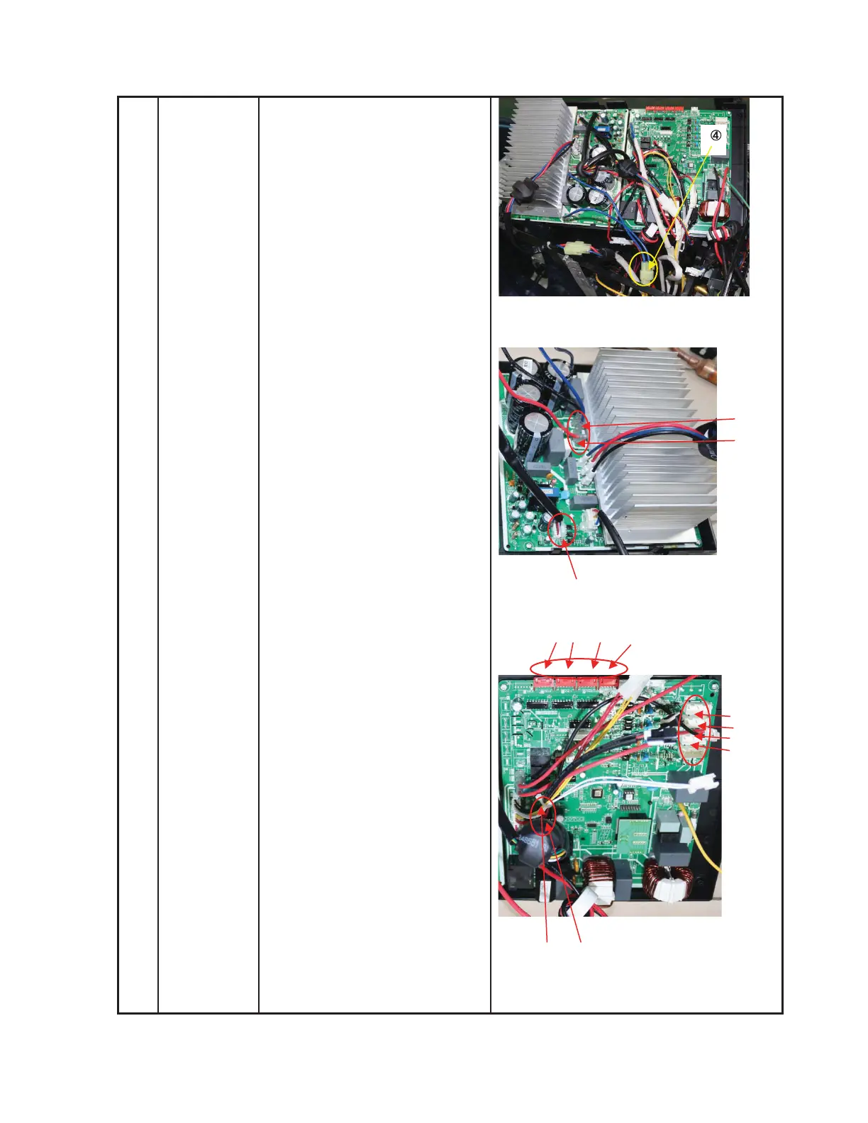
CN55-CN7(7p,white)
CN54-CN6(red)
CN53-CN5(black)
6) Remove the screws then
remove the driver board.
7) Disconnect the connectors
and wires from the PCB and
other parts.
Connectors:
CN8:T3/T4 temperature sensor
(2p/2p,white)
CN33: Discharge temperature sensor
(2p,white)
CN13:T2B-A,B,C,D temperature
sensor (2p/2p/2p/2p,white)
CN18/CN17/CN21/CN20: Electronic
expansion valve A,B,C,D
(6p/6p/6p,red/red/red)
CN30/CN29/CN28/CN27: S-A,S-B,S-C,
S-D (3p/3p/3p/3p,white)
CN9: High and low pressure switch
(2p/2p, white)
CN55
CN8 CN9
CN18/CN17/CN21/CN20
CN53
CN54
CN30/
CN29/
5) Disconnect the following
three connection wires
between the driver board
and PCB.
 Loading...