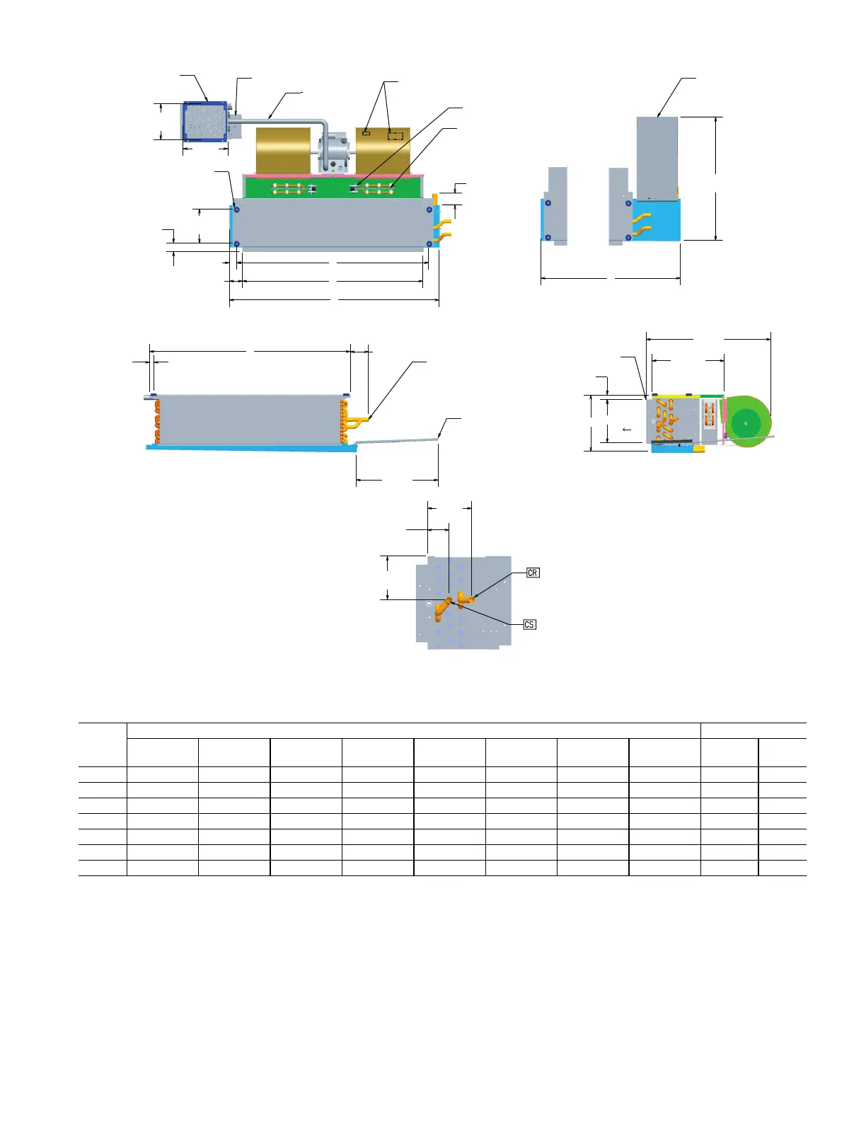
Fig. 6 — 42CA Horizontal Hideaway With Electric Heat Unit Dimensions
a. Right-hand units shown, left-hand opposite.
b. All dimensions are ± .25 [6]. Drawing not to scale.
c. Product specifications are subject to change without notice.
d. Drip lip recommended. Provided when valve package is ordered.
e. Control box size and position may vary. Consult factory.
f. Position may vary.
g. Service entrance is located on the rear of the control box with knockouts.
h. Units without service switch use the knockouts on the rear side of the control box.
i. Typical size 06 unit shown with 1-Motor and 2-Blower. Refer to table for variation.
j. See valve package supplemental for piping termination.
QTY/UNIT
A B C E F G H J Blower Motor
02 21-1/4 [540] 28-1/2 [724] 16 [406] 18-1/4 [464] 6-1/4 [159] 8-3/4 [222] 19-3/4 [502] 38 [965] 1 1
03 25-1/4 [641] 32-1/2 [826] 20 [508] 22-1/4 [565] 6-1/4 [159] 8-3/4 [222] 23-3/4 [603] 38 [965] 1 1
04 31-1/4 [794] 38-1/2 [978] 26 [660] 28-1/4 [718] 6-1/4 [159] 8-3/4 [222] 29-3/4 [756] 38 [965] 2 1
06 36-1/4 [921] 43-1/5 [1105] 31 [787] 33-1/4 [845] 7-1/2 [191] 10 [254] 34-3/4 [883] 38 [965] 2 1
08 43-1/4 [1099] 50-1/2 [1283] 38 [965] 40-1/4 [1022] 7-1/2 [191] 10 [254] 41-3/4 [1060] 38 [965] 2 1
10 57-1/4 [1454] 64-1/2 [1638] 52 [1321] 54-1/4 [1378] 7-1/2 [191] 10 [254] 55-3/4 [1416] 60 [1524] 4 2
12 65-1/4 [1657] 72-1/2 [1842] 60 [1524] 62-1/4 [1581] 7-1/2 [191] 10 [254] 63-3/4 [1619] 65 [1651] 4 2

 Loading...


