5
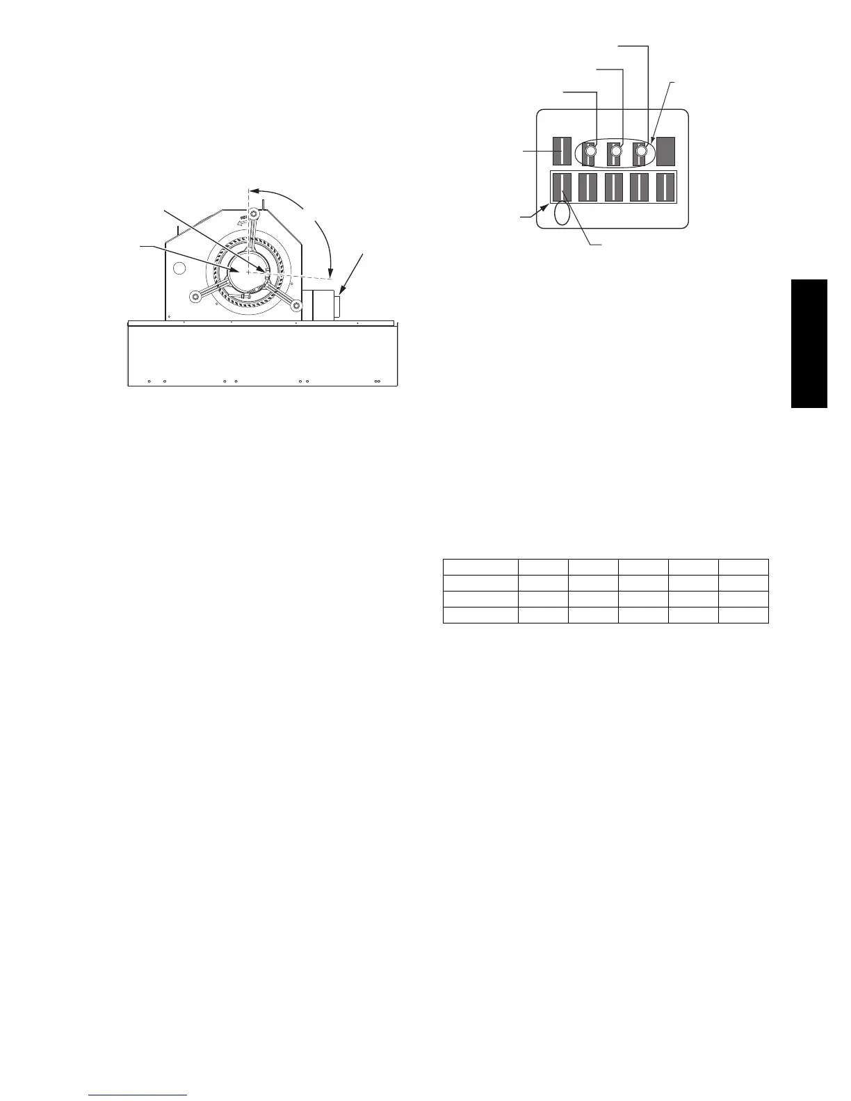
Supply Fan (Direct--Drive)
For unit sizes 04, 05 and 06, a direct--drive
forward --curved centrifugal blower wheel is an available
option. The motor has taps to provide the servicer with the
selection of one of five motor torque/speed ranges to best
match wheel performance with attached duct system. See
Fig. 5 and Fig. 6 .
ECM Motor
Motor Plug Position
(95° from vertical)
95°
ECM Power
Transformer
(460, 575v)
C09260
Fig. 5 -- Direct--Drive Supply Fan Assembly
ECM Motor — The direct--drive motor is an X13
Electronically Commutated Motor (ECM). An ECM
motor contains el ectronic circuitry used to convert
single--pha se line AC volt age into 3--phase DC voltage to
power the motor circuit. The motor circuit is a DC
brushless design with a perm anent magnet rotor. On the
X13 ECM Motor design, the electronic circuitry is
integral to the motor assembly and cannot be serviced or
replaced separately.
208/230V units use a 230V motor. 460V units use a 230V
motor with a stepdown transformer (mounted on the end
of the fan housing, see Fig. 5). 575V units use a 460V
motor with an autotransformer. Motor power voltage is
connected to motor terminals L and N (see Fig. 6 and
Fig. 7); ground is connec ted at terminal G. The motor
power voltage is ALWAYS present; it is not switched off
by a motor cont actor.
L2
YEL
Gnd
GRN/YEL
L1
BLU
C
12345
LGN
Motor
Power
Connections
Speed
Taps
Com
BRN
VIO
Default Connection
C09261
Fig. 6 -- ECM Motor Connectors
Evaluating motor speed — The X13 ECM Motor uses a
constant torque motor design. The motor speed is adjusted
by the motor control circuitry to maint ain the programmed
shaft torque. Consequently there is no specific speed value
assigned to each control tap setting. At the Position 5 tap,
the motor speed is approximately 1050 RPM (17.5 r/s) but
varies depending on fan wheel loading.
Selecting speed tap — The five communication terminals
are each programmed to provide a different motor torque
output. See Table 1. Factory default tap selection is
Position 1 for lowest torque/speed operation.
Table 1 – Motor Tap Programing
(p er cen t of full--load torque)
Unit Size Ta p 1 Ta p 2 Ta p 3 Ta p 4 Ta p 5
04 32 38 45 50 100
05 46 58 61 69 100
06 73 82 85 90 100
Factory Default: Tap 1 (VIO)
Selecting another speed:
1. Disconnect main power to the unit. Apply
lockout/tagout procedures.
2. Remove the default motor signal lead (VIO) from
terminal 1 at the motor communications terminal.
3. Reconnect the motor signal lead to the desired speed
(terminals 1 through 5).
4. Connect main power to the unit.
48HC

 Loading...


