11
Reassembly of Standard/Medium Motor and Fan Assembly
See Fig. 14.
NOTE: Refer to “Model Number Nomenclature” on page 66,
position 10 for specific unit requirements.
1. Place motor on flat surface.Install Heat shield on back of
motor.
2. If required, reinstall limit switch on stator with two plastic
fastener plugs (48TM005675).
3. Line up keying features on stator and motor and set stator
onto motor. Install four 1/4-20 x 1-in. screws
(AC67AP170) to attach stator to motor. Tighten to
50 in.-lb (5.65 Nm).
4. Set rotor onto motor flange. Install three 1/4-20 x 1-in.
screws (AC67AP170) to attach rotor to motor. Tighten to
50 in.-lb (5.65 Nm).
5. Set casing onto stator. Install four #10-16 x 3/4-in. screws
(AP13AD128) through U-Clips in casing. Tighten to
14 in.-lb (1.58 Nm).
6. Pull motor harness out through guide feature in stator if
not already completed.
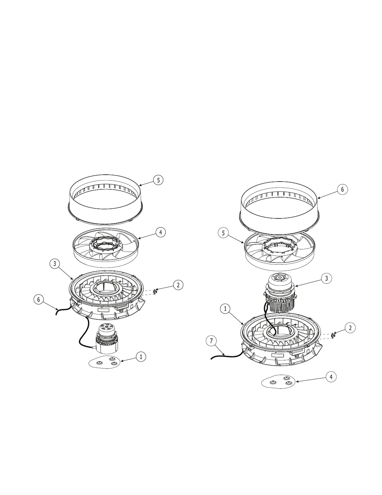
Fig. 14 — Standard/Medium Fan System
Re-Assembly
Reassembly of High Static Motor and Fan Assembly
See Fig. 15.
NOTE: Refer to “Model Number Nomenclature” on page 66,
position 10 for specific unit requirements.
1. Place stator on flat surface.
2. If required, reinstall limit switch on stator with two plastic
fastener plugs (48TM005675).
3. Line up keying features on stator and motor and set motor
onto stator. Motor wire Harness should align with guide
feature in stator. Install six 1/4-20 x 1-in. screws
(AC67AP170) to attach stator to motor. Tighten to
30 in.-lb (3.39 Nm).
4. Install Heat shield on back of motor.
5. Set rotor onto motor flange. Install three 1/4-20 x 1-in.
screws (AC67AP170) to attach rotor to motor. Tighten to
50 in.-lb (5.65 Nm).
6. Set casing onto stator. Install four #10-16 x 3/4-in. screws
(AP13AD128) through U-Clips in casing. Tighten to
14 in.-lb (1.58 Nm).
7. Pull motor harness out through guide feature in stator if
not already completed.
Fig. 15 — High Static Fan System
Re-Assembly
 Loading...


