5 - ELECTRICAL CONNECTION
Please refer to the certied dimensional drawings, supplied with
the unit.
5.1 - Power supply
The power supply must conform to the specication on the unit
nameplate. The supply voltage must be within the range specied
in the electrical data table. For connection details refer to the wiring
diagrams.
WARNING: Operation of the unit with an improper supply voltage or
excessive phase imbalance constitutes abuse which will invalidate
the Carrier warranty. If the phase imbalance exceeds 2% for
voltage, or 10% for current, contact your local electricity supplier
at once and ensure that the unit is not switched on until corrective
measures have been taken.
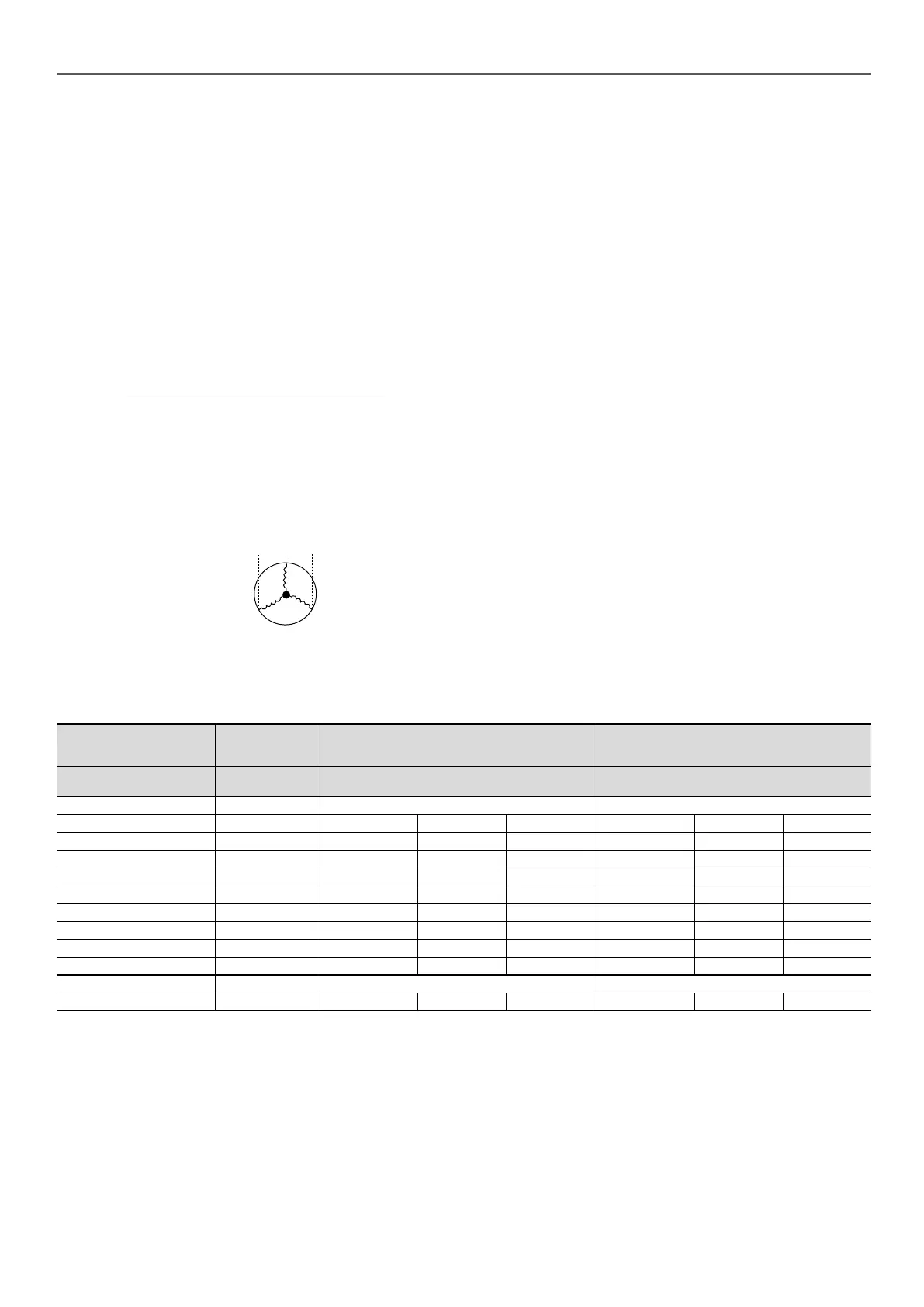
5.2 - Voltage phase imbalance (%)
100 x max. deviation from average voltage
Average voltage
Example:
On a 400 V - 3 ph - 50 Hz supply, the individual phase voltages
were measured to be:
AB = 406 V; BC = 399 V; AC = 394 V
Average voltage = (406 + 399 + 394)/3 = 1199/3
= 399.7 say 400 V
Calculate the maximum deviation from the 400 V average:
(AB) = 406 - 400 = 6
(BC) = 400 - 399 = 1
(CA) = 400 - 394 = 6
The maximum deviation from the average is 6 V. The greatest
percentage deviation is: 100 x 6/400 = 1.5 %
This is less than the permissible 2% and is therefore acceptable.
5.3 - Power connection/disconnect switch
30XW-V/30XWHV 580-880 units have one connection point
30XW-V/30XWHV 1150-1710:
• Standard unit: two connection points
• Unit with option 81: one connection point.
5.4 - Recommended wire sections
Wire sizing is the responsibility of the installer, and depends on the
characteristics and regulations applicable to each installation site.
The following is only to be used as a guide-line, and does not make
in any way liable. After wire sizing has been completed, using the
certied dimensional drawing, the installer must ensure easy
connection and dene any modications necessary on site. The
connections provided as standard for the eld-supplied power entry
cables to the general disconnect/isolator switch are designed for
the number and type of wires, listed in the second column of the
table below.
The calculations for favourable and unfavourable cases are based
on the maximum current for each unit (see electrical data tables).
For the design the standardised installation methods in accordance
with IEC 60364 are used: multicon-ductor PVC (70°C) or XLPE
(90°C) insulated cables with copper core; arrangement to comply
with table 52c of the above standard. The maximum temperature is
42°C. The given maximum length is calculated to limit the voltage
drop to 5%.
5.5 - Power cable entry
The power cables can enter the control box from above the unit.
A removable aluminium plate on the upper part of the control box
face allows introduction of the cables. Refer to the certified
dimensional drawing for the unit.
Minimum and maximum connectable wire sections
Max.
connectable
wire section
(1)
Calculation favourable case: Perforated
horizontal conduit (standardised routing No.
13) - XLPE insulated cable
Calculation unfavourable case: Closed
conduit (standard-ised routing No. 41) - PVC
insulated cable, if possible
30XW-V/30XWHV
Circuit(s) A/B
Section, mm²
(per phase)
Section
(2)
, mm²
(per phase)
Max. length,
m
Cable type Section
(2)
, mm²
(per phase)
Max. length,
m
Cable type
(3)
Units without option
580 2 x 240 1 x 120 250 XLPE 1 x 240 420 PVC
630 2 x 240 1 x 150 250 XLPE 2 x 150 450 PVC
810 2 x 240 1 x 185 250 XLPE 2 x 185 450 PVC
880 2 x 240 1 x 240 280 XLPE 2 x 240 480 PVC
1150 2 x 240/2 x 240 1 x 120/1 x 120 250/250 XLPE 2 x 150/2 x 150 520 PVC
1280 2 x 240/2 x 240 1 x 150/1 x 150 250/250 XLPE 2 x 185/2 x 185 510 PVC
1470 2 x 240/2 x 240 1 x 240/1 x 150 310/250 XLPE 2 x 240/2 x 185 520/510 PVC
1570 2 x 240/2 x 240 1 x 240/1 x 240 310/310 XLPE 2 x 240/2 x 240 530/530 PVC
1710 2 x 240/2 x 240 1 x 240/1 x 240 280/280 XLPE 2 x 185/2 x 185 400/400 XLPE
Units with option 81
1150 to 1710 4 x 240 2 x 240 280 XLPE 4 x 185 320 XLPE
(1) Connection capacities actually available for each machine, dened according to the connection terminal size, the control box access opening size and the available
space inside the control box.
(2) Selection simultation result considering the hypothesis indicated.
(3) If the maximum calculated section is for an XLPE cable type, this means that a selection based on a PVC cable type can exceed the connection capacity actually
available. Special attention must be given to the selection.
Note: The currents considered are given for a machine equipped with a hydraulic module operating at maximum current.
Motor
A
B
C
15
 Loading...