9 - MAJOR SYSTEM COMPONENTS AND OPERATION DATA
9.1 - Compressors
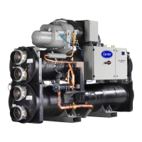
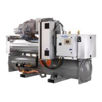
• 30XW-V/30XWHV units use 06T geared twin-screw
compressors equipped with a variable capacity slide valve
and controlled by a speed variator.
• Compressor capacity control is ensured by successive use of
speed variation (using a frequency variator) and swept volume
variation at the screws (using the slide valve).
• The combination of these two control modes permits ne
control of the unit capacity between 20% and 100%.
• The 06T compressor models used are:
06TUX483, 06TUX554, 06TVX680, 06TVX753
9.2 - Oil lter
The 06T screw compressor has an independent oil lter.
9.3 - Refrigerant
30XW-V/30XWHV units only use refrigerant R-134a.
9.4 - Lubricant
The 06T screw compressor is approved for use with lubricants:
• Carrier specication PP47-32
• Carrier specication PP47-13
9.5 - Oil supply solenoid valve
An oil supply solenoid valve is installed on the oil return line as
standard to isolate the compressor from oil flow when the
compressor is not operating. The oil solenoid valve is field
replaceable.
9.6 - Pressure vessels
9.6.1 - General
Monitoring during operation, re-qualication, re-testing and re-
testing dispensation:
• Follow the regulations on monitoring pressurised equipment.
• It is normally required that the user or operator sets up and
maintains a monitoring and maintenance le.
• If no regulations exist or to complement regulations, follow
the control programmes of EN 378.
• If they exist follow local professional recommendations.
• Regularly inspect the condition of the coating (paint) to
detect blistering resulting from corrosion. To do this, check
a non-insulated section of the container or the rust formation
at the insulation joints.
• Regularly check for possible presence of impurities (e.g.
silica grains) in the heat exchange uids. These maybe the
cause of the wear or corrosion by puncture.
• Filter the heat exchange uid check and carry out internal
inspections as described in EN 378, annexe C.
• In case of re-testing please refer to the maximum operating
pressure given on the unit nameplate.
• The reports of periodical checks by the user or operator must
be included in the supervision and maintenance le.
9.6.2 - Repair
Any repair or modication, including the replacement of moving
parts:
• must follow local regulations and be made by qualied
operators and in accordance with qualied procedures,
including changing the heat exchanger tubes.
• must be made in accordance with the instructions of the
original manufacturer. Repair and modification that
necessitate permanent assembly (soldering, welding,
expanding etc.) must be made using the correct proce-dures
and by qualied operators.
• An indication of any modication or repair must be shown
in the monitoring and maintenance le.
9.6.3 - Recycling
The unit is wholly or partly recyclable. After use it contains
refrigerant vapours and oil residue. It is coated by paint.
9.6.4 - Operating life
The evaporator and oil separator are designed for:
• prolonged storage of 15 years under nitrogen charge with
a temperature difference of 20 K per day.
• 452000 cycles (start-ups) with a maximum difference of 6
K between two neighbouring points in the vessel, based on
6 start-ups per hour over 15 years at a usage rate of 57%.
9.6.5 - Corrosion allowances:
Gas side: 0 mm
Heat exchange uid side: 1 mm for tubular plates in lightly alloyed
steels, 0 mm for stainless steel plates or plates with copper-nickel
or stainless steel protection.
9.6.6 - Evaporator
30XW-V/30XWHV units use a ooded multi-tube evaporator. The
water circulates in the tubes and the refrigerant is on the outside
in the shell. The tubes are 3/4” diameter copper with an enhanced
surface inside and out. There is just one water circuit with two
water passes (one pass with option 100C, please refer to chapter
6.6 “Number of passes”).
The evaporator shell has a polyurethane foam thermal insulation
and a water drain and purge.
It has been tested and stamped in accordance with the applicable
pressure codes. The maximum standard relative operating pressure
is 2100 kPa for the refrigerant-side and 1000 kPa for the water-side.
These pressures can be different depending on the code applied.
The water connection of the heat exchanger is a Victaulic
connection.
The products that may be added for thermal insulation of the
containers during the water piping connection procedure must be
chemically neutral in relation to the materials and coatings to which
they are applied. This is also the case for the products originally
supplied by Carrier.
9.6.7 - Condenser and oil separator
30XW-V/30XWHV units use a heat exchanger that is a combination
condenser and oil separator. It is mounted below the evaporator.
Discharge gas leaves the compressor and ows through an
external mufer to the oil separator, which is the upper portion of
the heat exchanger. It enters the top of the separator where oil is
removed, and then ows to the bottom portion of the vessel, where
gas is condensed and subcooled. The tubes are 3/4” or 1” diameter
internally and externally nned copper tubes.
There is just one water circuit with two water passes (one pass
with option 102C, please refer to chapter 6.6 “Number of passes”).
For the heat pumps the condenser shell can have a polyurethane
foam thermal insulation (option 86) and a water drain and purge.
It has been tested and stamped in accordance with applicable
pressure codes. The maximum standard relative operating pressure
is 2100 kPa for the refrigerant-side and 1000 kPa for the water-side.
These pressures can be different depending on the code applied.
The water connection of the heat exchanger is a Victaulic
connection.
24
 Loading...