33
11.5 - Field control wiring
IMPORTANT: Field connection of interface circuits may lead
to safety risks: any control box modication must maintain
equipment conformity with local regulations. Precautions
must be taken to prevent accidental electrical contact between
circuits supplied by different sources:
• The routing selection and/or conductor insulation
characteristics must ensure dual electric insulation.
• In case of accidental disconnection, conductor xing
between different conductors and/or in the control box
prevents any contact between the conductor ends and
an active energised part.
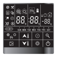
Refer to the 30RB/30RQ Touch Pilot Junior control manual and
the certied wiring diagram supplied with the unit for the eld
control wiring of the following features:
• Water heat exchanger pump interlock (mandatory)
• Remote on/off switch
• Demand limit external switch
• Remote dual set point
• Alarm, alert and operation report
• Heating/cooling selection
11.6 - Power supply
ATTENTION: After the unit has been commissioned, the power
supply must only be disconnected for quick maintenance
operations (one day maximum). For longer maintenance
operations or when the unit is taken out of service and stored
(e.g.duringthewinteroriftheunitdoesnotneedtogenerate
cooling) the power supply must be main-tained to ensure
supplytotheheaters(compressoroilcrankcaseheaters,unit
frost protection).
After all possible options have been connected, the trans-former
ensures the availability of a usable 24 VA or 1 A power reserve for
the control circuit on site.
11 - ELECTRICAL CONNECTION

 Loading...


