4
ACCESSORIES LIST
The EconoMi$er IV assembly has several field-installed
accessories available to optimize performance. Refer to Table 3
for authorized parts.
VERTICAL INSTALLATION
These economizers are designed to work in both a vertical and
horizontal applications. These instructions are for a vertical
installation.
1. Turn off unit power supply and install lockout tag.
2. Prepare the unit for economizer installation:
a. For units with two position damper installed, remove the
outside air hood. Unplug the damper actuator and
remove assembly from unit.
b. For units with manual damper installed, remove the
manual damper and hood.
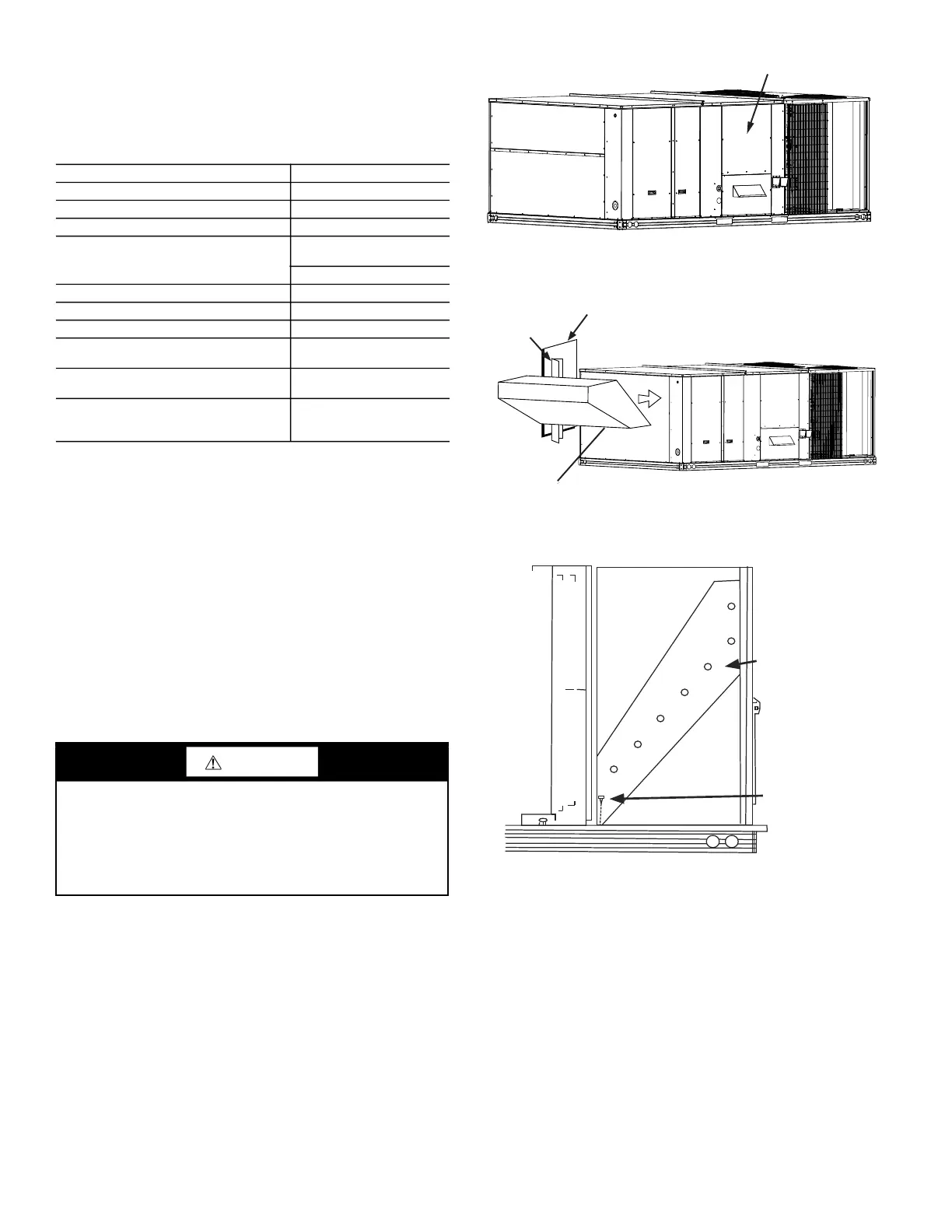
3. Remove the upper panel and bottom panel (provided with the
HVAC unit) on the end of the unit to expose the return
section. (See Fig. 2.) Save the screws for use later when
replacing the panel. The panels can be discarded.
4. Remove the unit's left side corner post and left side panel
from the unit to allow for easy economizer installation. (See
Fig. 3.)
5. Install economizer, as shown in Fig. 3, into the return air
section of the unit. Be careful not to pinch the wires during
installation. The bottom of the economizer will rest on the
base of the unit. (See Fig. 4.)
6. Reinstall the left side corner post on to the unit. Note the
corner post will sit behind the economizer flange. (See
Fig. 5.) Screw through the corner post and through the
economizer. (See Fig. 5 and 6.)
Fig. 2 — Upper and Bottom Panel on End of Unit
Fig. 3 — Unit Left Side Panel and Corner Post
Fig. 4 — Side View
7. Insert provided screw through the bottom left rear of the
economizer and into the unit base. (See Fig. 4.) Reinstall the
unit's left side panel.
8. Before the economizer is secured in place on the right hand
side, remove and save the 12-pin jumper plug from the unit
wiring harness. (See Fig. 7.) Insert the economizer plug into
the unit wiring harness plug.
NOTE: The 12-pin jumper plug should be saved for future use in
the event that the EconoMi$er IV assembly is removed from the
unit. The jumper plug is not needed as long as the EconoMi$er IV
assembly is installed.
Table 3 — EconoMi$er IV Field-Installed Accessories
DESCRIPTION PART NUMBER
Power Exhaust 208-230 v 3 Ph CRPWREXH068A00
Power Exhaust 460 v 3 Ph CRPWREXH069A00
Power Exhaust 575 v 3 Ph CRPWREXH070A00
Outdoor Air Enthalpy Sensor
HH57AC078
(Carrier and Bryant only)
AXB078ENT (ICP only)
Indoor Air Enthalpy Sensor CRENTDIF004A00
Return Air CO
2
Sensor (4 to 20 mA) CRCBDIOX005A00
CO
2
Room Sensor (4 to 20 mA) 33ZCSENC02
Aspirator Box for Duct Mount CO
2
(4 to 20 mA)
33ZCASPCO2
Space Temperature and CO
2
Room
Sensor with Override (4 to 20 mA)
33ZCT55CO2
Space Temperature and CO
2
Room
Sensor with Override and Set Point
(4 to 20 mA)
33ZCT56CO2
CAUTION
PERSONAL INJURY HAZARD
Failure to follow this caution can result in personal injury and
damage to the unit.
Cover the duct opening as a precaution so objects cannot fall
into the return duct opening. Be sure to remove the cover when
installation is complete.
Upper End Panel
Shipped On
Base Unit
Bottom Panel
Shipped On
Base Unit
Indoor Fan Panel
UNIT’S LEFT
SIDE PANEL
ECONOMI$ER IV
LEFT
CORNER
POST
Left
Corner
Post
Unit’s Left
Side Panel
Economizer IV
Economizer
Screw Economizer
To B as e
 Loading...