8
Fig. 15 — Economizer Wiring Diagram
HORIZONTAL INSTALLATION
These economizers are designed to work in both vertical and
horizontal applications. These instructions are for a horizontal
application.
The unit has a horizontal duct opening next to the horizontal
supply duct opening. However, in this application, with an
economizer, the horizontal duct will actually come into the unit
underneath the outdoor air hood. (See Fig. 16.)
1. Turn off unit power supply and install lockout tag.
2. Prepare the unit for economizer installation:
a. For units with 2 position damper installed, remove the
outside air hood. Unplug the damper actuator and
remove assembly from unit.
b. For units with manual damper installed, remove the
manual damper and hood.
3. Remove the upper panel and bottom panel (provided with the
HVAC unit). On the end of the unit to expose the return
section. (See Fig. 17.) Save the screws for use later when
replacing the panel. The panels can be discarded.
4. Remove the unit's left side corner post and left side panel
from the unit to allow for easy economizer installation. (See
Fig. 18.)
NOTE: The unit's left side panel has a duct opening in it, but this
panel / duct opening will not be used in this application and can be
discarded.
5. Install economizer, as shown in Fig. 19, into the return air
section of the unit. Be careful not to pinch the wires during
installation. Bottom of economizer will rest on the base of the
unit. (See Fig. 20.)
6. Reinstall the left side corner post on to the unit. Note the
corner post will sit behind the economizer flange. (See
Fig. 21.) Screw through the corner post and through the
economizer. (See Fig. 21 and 22.)
7. Insert provided screw through the bottom left rear of the
economizer and into the unit base. (See Fig. 20.) Install the
new (provided) left side panel - without the duct opening on
the unit.
8. Before the economizer is secured in place on the right hand
side, remove and save the 12-pin jumper plug from the unit
wiring harness. Insert the EconoMi$er IV plug into the unit
wiring harness plug. (See Fig. 23.)
NOTE: The 12-pin jumper plug should be saved for future use in
the event that the EconoMi$er IV assembly is removed from the
unit. The jumper plug is not needed as long as the EconoMi$er IV
assembly is installed.
POTENTIOMETER
POWER EXH
MINIMUM POS.
DCV MAX.
DCV SET
ENTHALPY
DEFAULTS SETTINGS:
MIDDLE
FULLY CLOSED
MIDDLE
MIDDLE
C SETTING
(ACCESSORY)
REMOTE MIN
POSITION POT
REMOTE POT (135 ohm)
(FIOP / ACCESSORY)
IAQ SENSOR
2
8
7
1
BRN
RED
RED
BLU
BLK
BLK
WHT
BLK
BLK
BLK
GRA
GRA
GRA
GRA
GRA
GRA
YEL
ORN
ORN
ORN
PNK
PNK
YEL
YEL
YEL
BLU
BLU
BLU
BLU
BLU
PNK
PNK
PNK
VIO
VIO
VIO
BLK
BRN
BRN
BRN
BRN
OAT TEMP /
ENTHALPY SENSOR
(ACCESSORY)
RAT/ENTHALPY SENSOR
+
5
AQ1
AQ
SO+
SO
SR+
SR
620Ω
N1
N
P1
T1
P
T
2V
2V
2V
10V
10V
10V
EXH
SET
EXH
MIN
POS
OPEN
DCV
MAX
DCV
SET
DCV
FREE
COOL
A
B
C
D
RED
RED
RED
RED
RED
RED
BRN
BRN
ECONOMISER
IV BOARD
TR
TR1
24
Vac
HOT
24Vac
COM
-
+
1
1
1
2
2
2
5
5
9
12
8
10
11
6
7
4
4
3
3
1
2
5
9
12
8
10
11
6
7
4
3
1
2
5
9
12
8
10
11
6
7
4
3
3
EF EF1
ECONOMIZER
MOTOR
LA
(NOT USED)
(NOT USED)
(NOT USED)
ESL
VIO
SAT
(FIOP / ACCY)
ECONOMIZER
PL6 - R
FOR STD
UNIT PL6
TAN
TO PWR EXHAUST
ACCESSORY
ECONOMIZER NOTES:
1. 620 OHM, 1 WATT 5% RESISTOR SHOULD BE REMOVED ONLY WHEN
USING DIFFERENTIAL ENTHALPY OR DRY BULB.
2. IF A SEPARATE FIELD SUPPLIED 24V TRANSFORMER IS USED FOR THE
IAQ SENSOR POWER SUPPLY, IT CANNOT HAVE THE SECONDARY OF THE
TRANSFORMER GROUNDED.
3. FOR FIELD INSTALLED REMOTE MINIMUM POSITION POT.
REMOVE BLACK WIRE JUMPER BETWEEN P AND P1 AND SET
CONTROL MINIMUM POSITION POT TO THE MINIMUM POSITION.
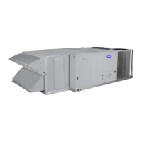
ECONOMIZER (FIOP / ACCESSORY)
Economizer Unit Without Economizer
 Loading...