7
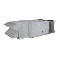
15. Install the hood assembly on to the unit (see Fig. 12 and 13).
16. Through the outdoor air hood, review and adjust the
EconoMi$er IV controller settings. See “Operation” section
of this manual for details.
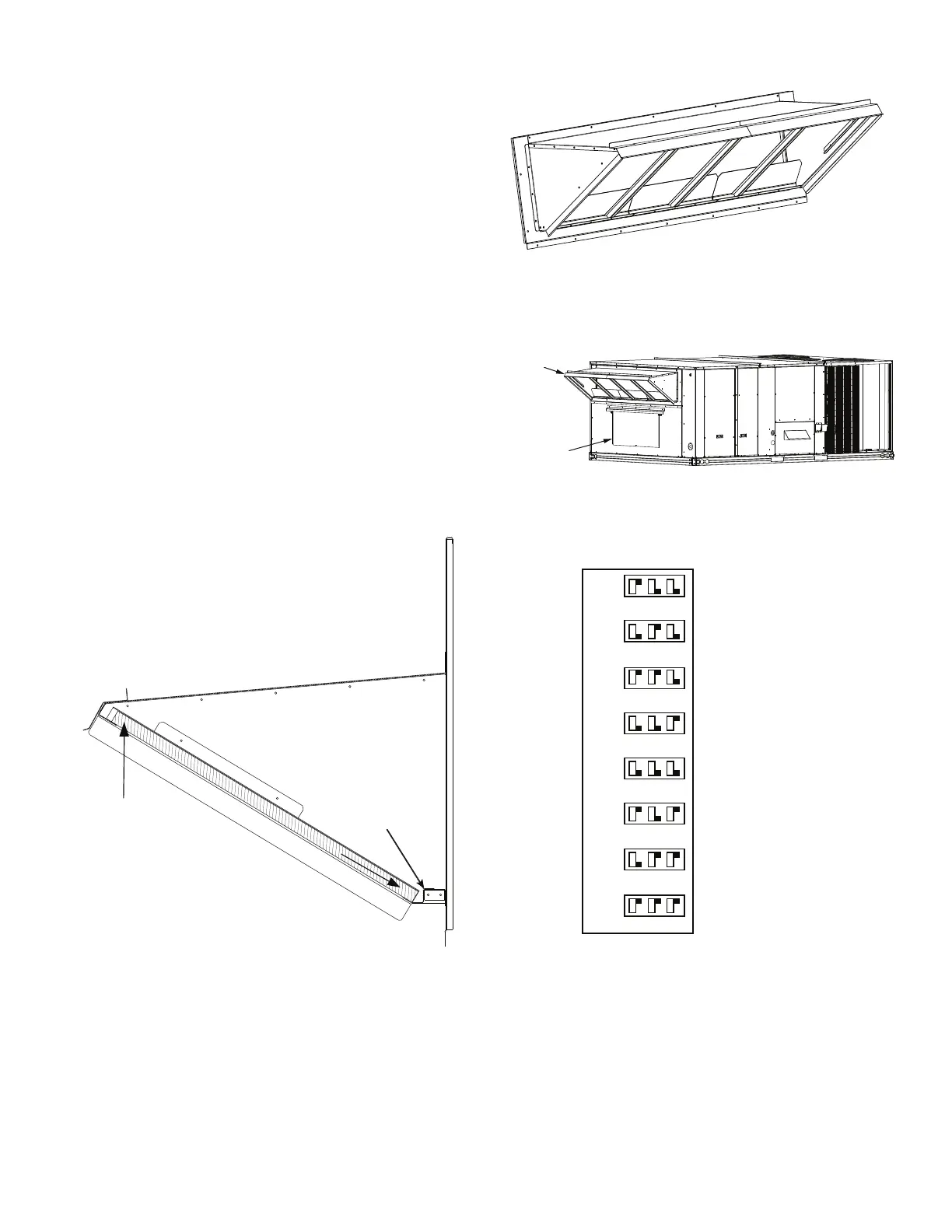
a. The standard EconoMi$er IV controller has a factory
setting of 63°F for the outdoor air temperature
changeover and 55°F (fixed) for the supply air
temperature sensor. The outdoor air temperature
changeover setting is adjusted on the sensor by setting
the dip switches on the sensor. (See Fig 14.) The ABCD
potentiometer on the controller should be set to the “D”
position.
b. The low temperature compressor lockout switch is fixed
at 42°F.
c. The minimum position for the outdoor air damper can
be configured for specific job requirements at the
controller. When not using with a CO
2
sensor, the DCV
Max potentiometer on the controller must be fully
closed (CCW) for the Minimum Position potentiometer
to function correctly.
d. Settings for the optional outdoor enthalpy sensor, indoor
enthalpy sensor, power exhaust, and CO
2
sensor can be
configured at the controller.
17. Install the hood screens and other approved EconoMi$er IV
accessories.
NOTE: See Fig. 15 for wiring diagram.
Fig. 11 — Outdoor Air Screen Installation
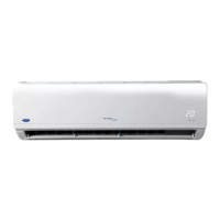
Fig. 12 — Completed Hood Assembly
Fig. 13 — Hood Assembly Installed on Unit
Fig. 14 — Selectable Temperature Options
Insert
Air Screen
Slide
Into
Position
Outdoor
ir Hood
Relief Damper
ON
OFF
1
2 3
1
2 3
1
2 3
1
2 3
1
2 3
1
2 3
1
2 3
1
2 3
ON
OFF
ON
OFF
ON
OFF
ON
OFF
ON
OFF
ON
OFF
ON
OFF
DIP SWITCH
POSITION
CHANGEOVER
TEMPERATURE
48°F
53°F
55°F
58°F
63°F
68°F
73°F
78°F
 Loading...