DLCLRC: Installation Instructions
Manufacturer reserves the right to change, at any time, specifications and designs without notice and without obligations.
14
ELECTRICAL DATA
Table 9 — Electrical Data
*Permissible limits of the voltage range at which the unit will operate satisfactorily.
LEGEND
FLA - Full Load Amps
MCA - Minimum Circuit Amps
MOCP - Maximum Over-Current Protection
RLA - Rated Load Amps
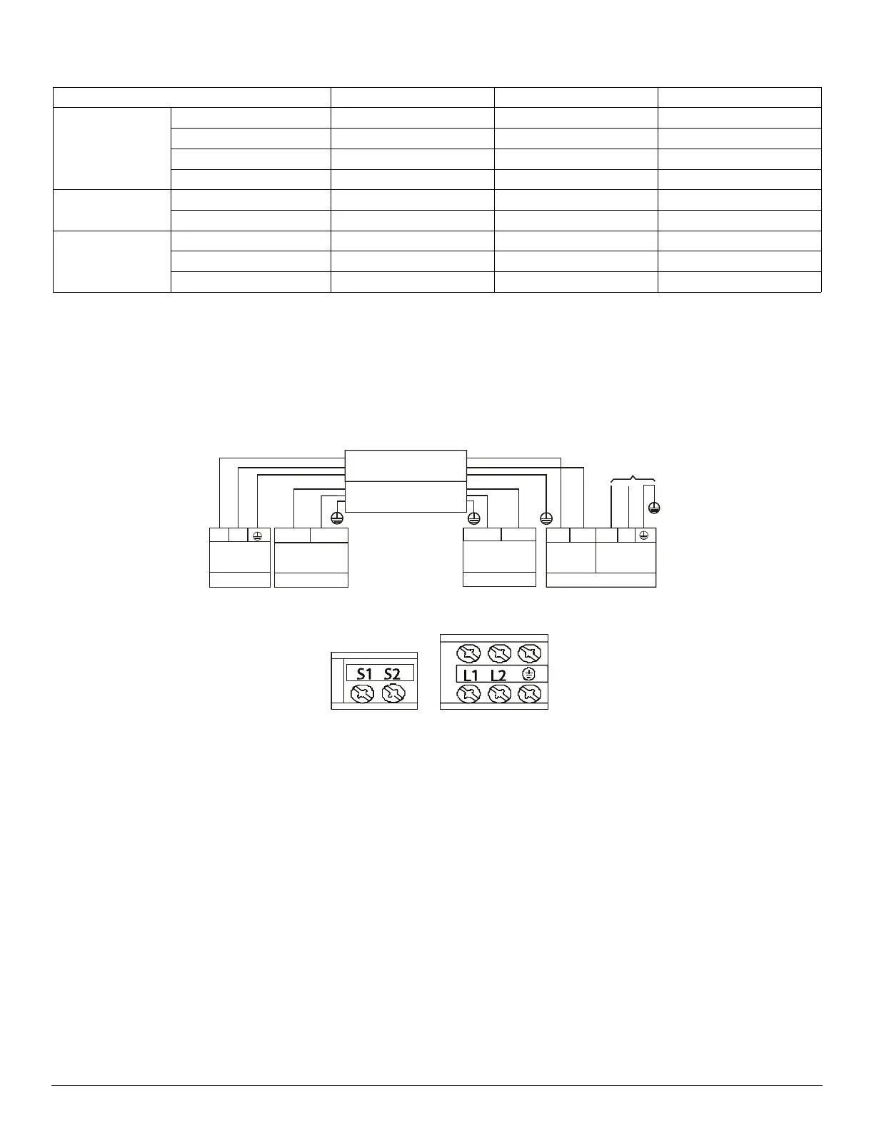
CONNECTION DIAGRAMS
Fig. 22 — Connection Diagram Sizes 36K - 58K
Fig. 23 — Control and Power Terminals on Indoor Unit Sizes 36K - 58K
NOTES:
1. Do not use the thermostat wire for any connection between indoor and outdoor units.
2. All connections between indoor and outdoor units must be as shown in Figure 22. The connections are sensitive to polarity and will result in a
fault code.
OUTDOOR UNIT SIZE 36K 48K 58K
Power Supply
208/230 - 1 - 60 208/230 - 1 - 60 208/230 - 1 - 60
Max – Min* Oper. Voltage 253 - 187 253 - 187 253 - 187
MCA302535
MOCP 50 50 50
Compressor
Volts- PH- Hz 208/230 - 1 - 60 208/230 - 1 - 60 208/230 - 1 - 60
Rated Current (RLA) 22 23.5 25
Outdoor Fan Motor
FLA 1.21 1.17 1.5
Rated HP 0.16 0.14 0.11
Output 120 85 85
208-230-1-60
L1
L2
FIELD POWER SUPPLY
Indoor Unit
Power Supply
Low voltage
Nonpolar RS-485
communication
208-230-1-60
Nonpolar RS-485
Low voltage
communication
Outdoor Unit
208-230-1-60
Power Supply
SHIELDED WIRE CONNECTING
OUTDOOR TO INDOOR
To Indoor Unit
Power Supply
S1
S2
L1
(1)L1
(2)L2
L2
P(S1)
GND
Q(S2)
CONNECTING CABLE
OUTDOOR TO INDOOR
 Loading...