DLCLRC: Installation Instructions
Manufacturer reserves the right to change, at any time, specifications and designs without notice and without obligations.
8
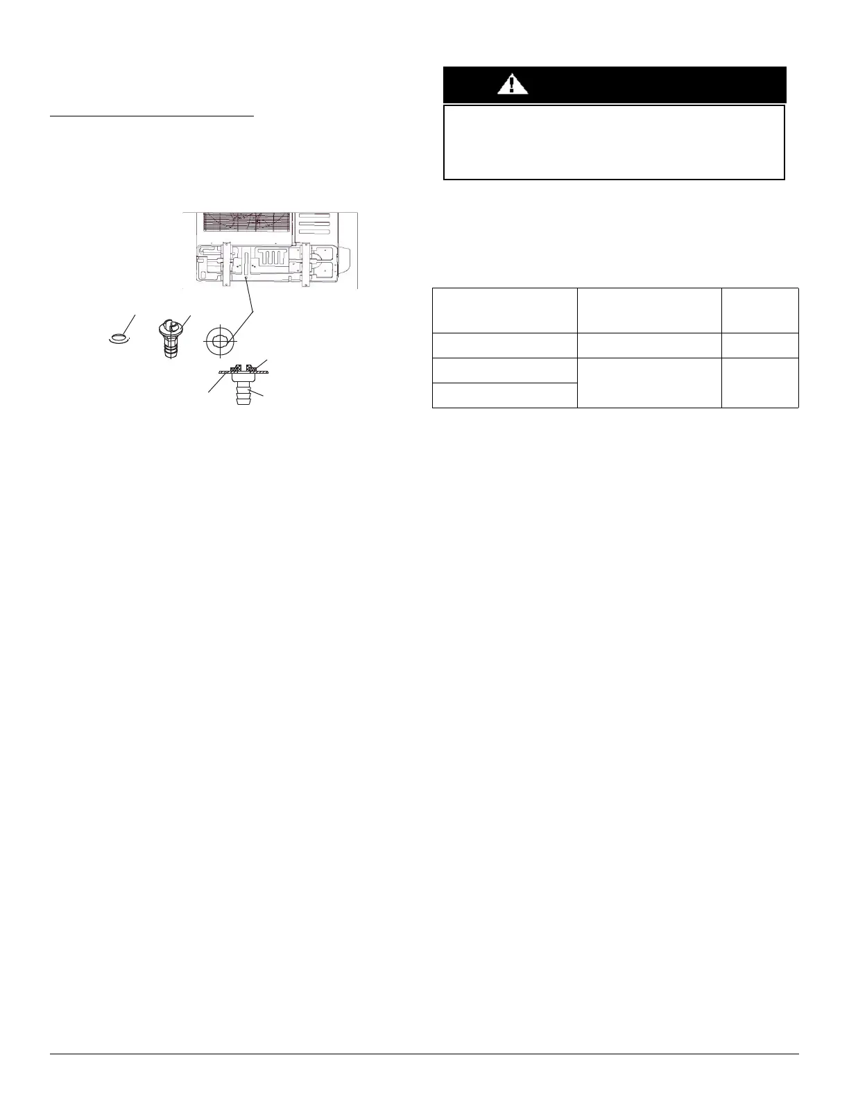
Step 3 - Condensate Drain Installation
Install drains must meet local sanitation codes.
Install the outdoor unit drain joint
Fit the seal into the drain joint, then insert the drain joint into the base pan
hole of the outdoor unit. Rotate 90° to securely assemble them. Connect
the drain joint with an extension drain hose to avoid condensate from
draining off the outdoor unit during the heating mode.
Fig. 9 —Drain Joint
NOTE: Images are for illustration purposes only.
NOTE: Basepan built-in with multiple holes for proper
draining during defrost. For applications where it is
required to seal these holes, and re-direct the
condensate drain, rubber plugs are available through
RCD.
Table 5 — Base Pan Base Rubber Plugs
Seal
Base pan hole
Drain joint
Seal
Base pan
Drain
joint
Outdoor Unit Model
Number
Per Unit
Base Pan Base Rubber
Plugs RCD Part Number
Quantity
DLCLRCQ36AA3 12600801A00117 5
DLCLRCQ48AA3
12600801A00118 5
DLCLRCQ58AA3
EQUIPMENT DAMAGE HAZARD
In cold climates, ensure the drain hose is as vertical as possible to
ensure swift water drainage. If water drains too slowly, it can freeze
in the hose and flood the unit.
CAUTION