DLCLRC: Installation Instructions
Manufacturer reserves the right to change, at any time, specifications and designs without notice and without obligations.
15
START-UP
Test Operation
Perform a test operation after completing a gas leak and electrical safety
check. See the indoor unit installation instructions and owner's manual for
additional start up information.
System Checks
1. Conceal the tubing where possible.
2. Ensure the drain tube slopes downward along its entire length.
3. Ensure all tubing and connections are properly insulated.
4. Fasten the tubes to the outside wall, when possible.
5. Seal the hole through which the cables and tubing pass.
Outdoor Unit
Are there unusual noises or vibrations during operation?
Explain the Following Item to the Customer (with the aid of
the Owner's Manual):
• Explain unit care and maintenance.
IMPORTANT: Present the installation instructions to the
customer.
CARE AND MAINTENANCE
To help ensure high performance and minimize possible equipment
failure, periodic maintenance must be performed on this equipment.
Maintenance frequency may vary depending upon geographic areas.
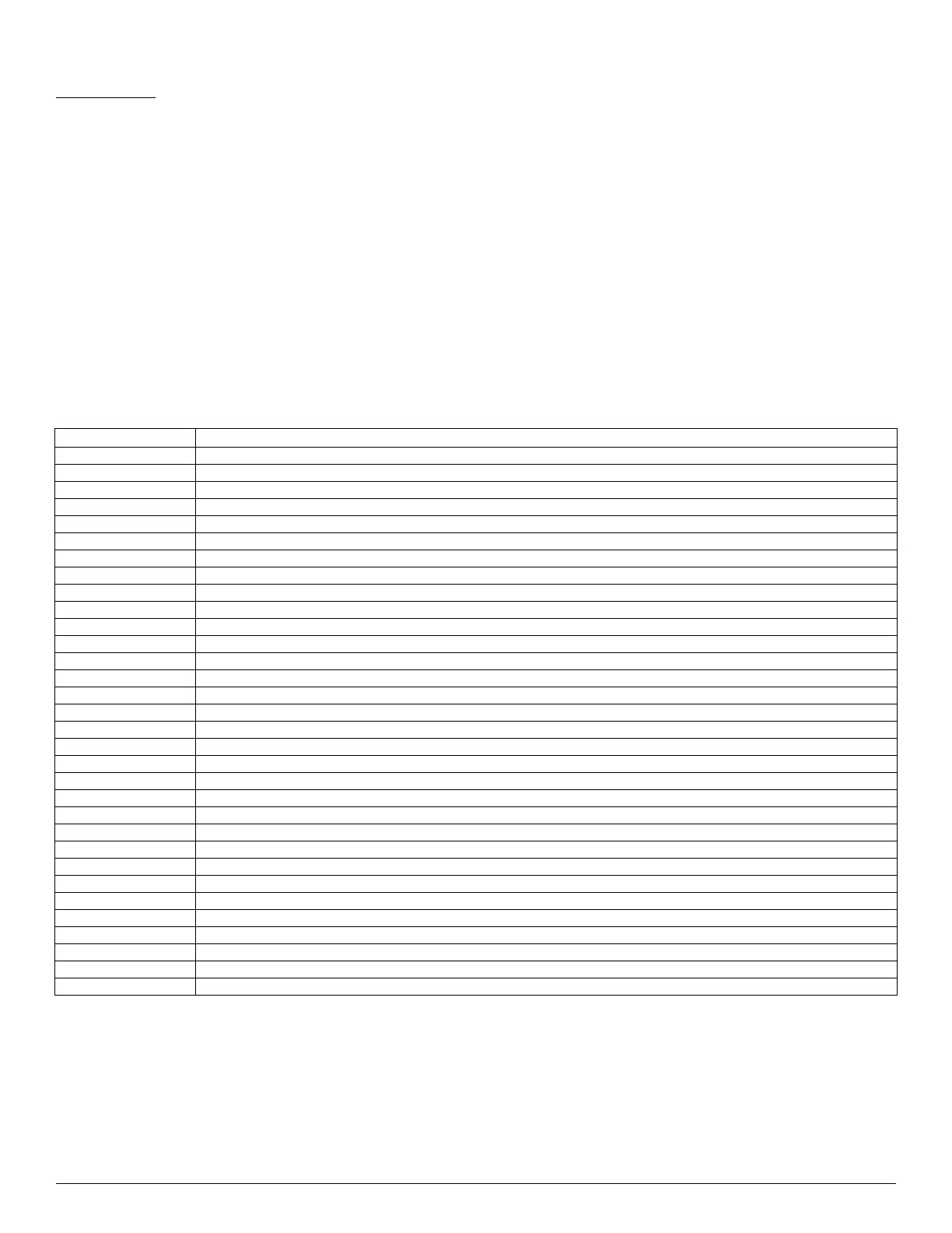
OUTDOOR UNIT DIAGNOSTIC GUIDES
For ease of service, the systems are equipped with a diagnostic code display LEDs on both the indoor and outdoor units. The outdoor diagnostic is
displayed on the outdoor unit microprocessor board. There may be a few error codes displayed in the indoor unit that might relate to the outdoor unit's
problems. If possible, always check the diagnostic codes displayed on the indoor unit first. The diagnostic codes displayed on the outdoor units are
listed on Table 10.
Table 10 — Unit Diagnostic Guides
For additional diagnostic information, refer to the service manual.
DISPLAY LED STATUS
EL01 Communication malfunction between the indoor and outdoor units
EC50 Outdoor temperature sensor error
EC51 Outdoor EEPROM error
EC52 Condenser coil temperature sensor (T3) malfunction
EC53 Outdoor ambient temperature sensor (T4) malfunction
EC54 Compressor discharge temperature sensor TP is on open circuit or has short circuited
EC55 Outdoor IPM module temperature sensor malfunction
EC07 Outdoor DC fan motor malfunction/fan speed out of control
EC71 Over current failure of the outdoor DC fan motor
EC72 Lack phase failure of the outdoor DC fan motor
PC00 Inverter module (IPM) protection
PC02 Top temperature protection of compressor
PC06 Discharge temperature protection of compressor
PC08 Outdoor overcurrent protection
PC0A High temperature protection of condenser
PC0F PFC module protection
PC0L Low temperature protection of the outdoor unit
PC10 Outdoor unit low AC voltage protection
PC11 Outdoor unit main control board DC bus high voltage protection
PC12 Outdoor unit main control board DC bus high voltage protection /341 MCE error
PC30 System high pressure protection
PC31 System low pressure protection
PC40 Communication error between the outdoor main chip and compressor driven chip
PC42 Compressor start failure of the outdoor unit
PC43 Outdoor compressor lack phase protection
PC44 Outdoor unit zero speed protection
PC45 Outdoor unit IR chip drive failure
PC46 Compressor speed has been out of control
PC49 Compressor overcurrent failure
PH90 High temperature protection of the evaporator
PH91 Low temperature protection of the evaporator
LC06 High temperature protection of the inverter module (IPM)
 Loading...