12
right column of Table 4 shows that (--) 12Vdc should be
present between Pin No. 14 and Pin No. 1 (common) on the
16--pin connector.
2. Set meter to read DC voltage. Place meter leads between
Pins No. 1 (common) and No. 14 and check for (--) 12Vdc.
If signal is present, the problem is in the module or motor. If
signal is not present, the problem is either in wiring harness
or Easy Select Board.
These steps can be repeated for other modes of operation.
To check Easy Select Board:
1. Leave jumper wire in place between R and Y/Y2.
2. Check Table 4 under Volt Meter on Easy Select Board
Plug column and row for Pin No. 14 on motor plug to see
pin number on Easy Select Board that should have voltage.
The correct pin is No. 2. The column on far right will show
voltage that should be present between Pin No. 2 and Pin
No. 9 (common).
3. Place meter leads between Pins No. 2 and No. 9 on Easy
Select Board and check for (--) 12Vdc.
4. If voltage is present, the wiring harness is bad. If not, the
Easy Select Board is bad.
Verify Motor Winding Section:
Before proceeding with module replacement, check the following
to ensure motor winding section is functional. With control module
removed and unplugged from winding section:
1. The resistance between any two motor leads should be sim-
ilar.
2. The resistance between any motor lead and the unpainted
motor end plate should be greater than 100,000 ohms.
If motor winding fails one of these tests, it is defective and must be
replaced.
F. Accessories
AUXILIARY TERMINALS
The AUX and HUM terminals on the Easy Select Board are tied
directly to the G terminal, and provide a 24--Vac signal whenever
the G terminal is energized (See Fig. 8). During Superdehumidify
mode, the G signal is not present and the auxiliary terminals are not
energized. If the installation includes the use of this operating
mode, do not use these terminals to control accessories. See
Electronic Air Cleaner and Humidifier sections for further
information.
ELECTRONIC AIR CLEANER CONNECTIONS
The AUX1 and AUX2 terminals are not always energized during
blower operation, as described above. When using an electronic air
cleaner with the FV4 fan coil, use Airflow Sensor. The airflow
sensor turns on electronic air cleaner when the fan coil blower is
operating.
HUMIDIFIER / HUMIDISTAT CONNECTIONS
Easy Select Board terminals HUM1 and HUM2 are provided for
direct connection to the low--voltage control of a humidifier
through a standard humidistat. These terminals are energized with
24Vac when G thermostat signal is present. Alternately, the 24--Vac
signal may be sourced from the W and C terminal block
connections when electric heaters are used as primary heating
source. When using a Thermidistat Control, Zone Perfect Plus,
or Comfort Zone II, the 24--Vac signal may be source directly from
the Thermidistat HUM terminal.
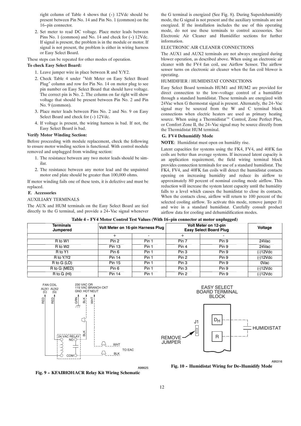
G. FV4 Dehumidify Mode
NOTE: Humidistat must open on humidity rise.
Latent capacities for systems using the FK4, FV4, and 40FK fan
coils are better than average systems. If increased latent capacity is
an application requirement, the field wiring terminal block
provides connection terminals for use of a standard humidistat. The
FK4, FV4, and 40FK fan coils will detect the humidistat contacts
opening on increasing humidity and reduce its airflow to
approximately 80 percent of nominal cooling mode airflow. This
reduction will increase the system latent capacity until the humidity
falls to a level which causes the humidistat to close its contacts.
When the contacts close, airflow will return to 100 percent of the
selected cooling airflow. To activate this mode, remove jumper J1
and wire in a standard humidistat. Carefully consult product
airflow data for cooling and dehumidification modes.
Table 4 – FV4 Motor Control Test Values (With 16--pin connector at motor unplugged)
Term ina l s
Jumpered
VoltMeteron16-pinHarnessPlug
Volt Meter on 12-pin
Easy Select Board Plug
Voltage
+ - + -
RtoW1 Pin 2 Pin 1 Pin 7 Pin 9 24Vac
RtoW2 Pin 13 Pin 1 Pin 4 Pin 9 24Vac
RtoY1 Pin 6 Pin 1 Pin 3 Pin 9 (-)12Vdc
RtoY/Y2 Pin 14 Pin 1 Pin 2 Pin 9 (-)12Vdc
RtoG(LO) Pin 15 Pin 1 Pin 3 Pin 9 0V ac
RtoG(MED) Pin 6 Pin 1 Pin 3 Pin 9 (-)12Vdc
RtoG(HI) Pin 14 Pin 1 Pin 2 Pin 9 (-)12Vdc
24 VAC RELAY
FAN COIL
230 VAC OR
115 VAC BRANCH CKT