17
control cannot discern the difference between an open sensor or if a
sensor is not installed.
F. Emergency Heating and Cooling Modes
Fan coil control can provide emergency heating or cooling using a
common heat/cool thermostat in the event that there are no system
communications, fault is in User Interface and no replacement is
immediately available.
To activate these modes, the thermostat and outdoor unit must be
wired as a common heating/cooling system to fan coil control
RYWC terminals. Fan coil control must be powered and displaying
Status Code 16, System Communication Fault.
NOTE: These emergency modes do not provide the level of
comfort and efficiency expected by the consumer and should only
be activated when User Interface cannot be replaced immediately.
FE4A FAN COIL SEQUENCE OF OPERATION
The FE4A fan coil is designed for installation with a
communicating User Interface. This fan coil will not respond to
commands provided by a common thermostat except under certain
emergency situations described in the Start Up and
Troubleshooting sub--section.
The User Interface uses temperature; humidity and other data
supplied from indoor and outdoor system components to control
heating or cooling system for optimum comfort.
FE4A ADVANCED TROUBLESHOOTING:
Status
LED
Communication
LED
Motor
LED
A13030
Fig. 12 -- FE4A Circuit Board LED Locations
Troubleshooting the FE Fan Coil Circuit Board:
--Production Unit circuit board Fan Coil part number HK38EA011
--RCD Replacement circuit board HK38EA012
--Older circuit board part numbers HK38EA006 and HK38EA009
Primary test that should be performed:
Motor Line Voltage Check
1. Turn off power (240V).
2. Remove Plug 3 from ECM motor
3. Turn on power.
4. Check Plug 3, terminals 4 and 5, to ensure there are 240V.
5. Turn off power.
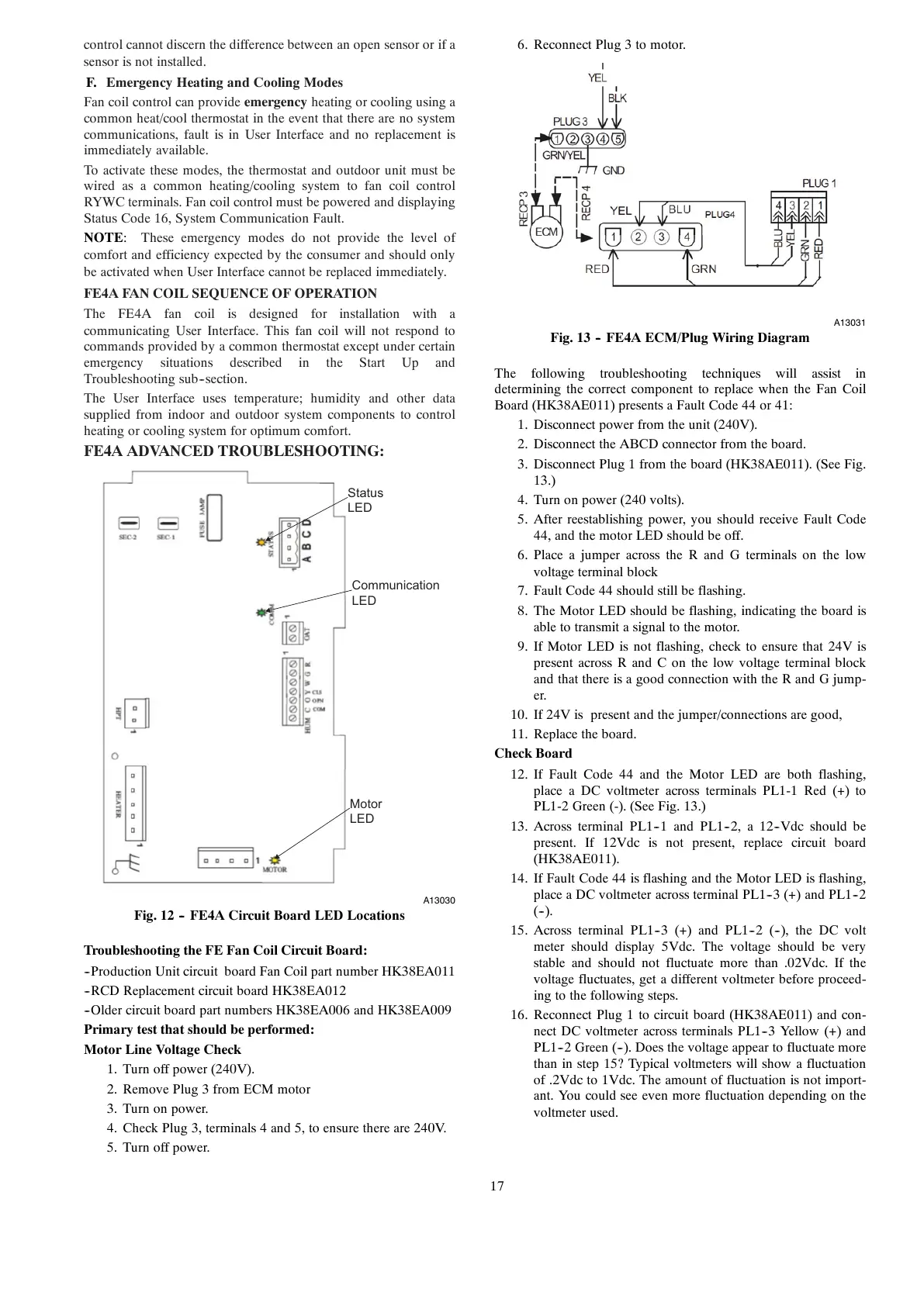
6. Reconnect Plug 3 to motor.
A13031
Fig. 13 -- FE4A ECM/Plug Wiring Diagram
The following troubleshooting techniques will assist in
determining the correct component to replace when the Fan Coil
Board (HK38AE011) presents a Fault Code 44 or 41:
1. Disconnect power from the unit (240V).
2. Disconnect the ABCD connector from the board.
3. Disconnect Plug 1 from the board (HK38AE011). (See Fig.
13.)
4. Turn on power (240 volts).
5. After reestablishing power, you should receive Fault Code
44, and the motor LED should be off.
6. Place a jumper across the R and G terminals on the low
voltage terminal block
7. Fault Code 44 should still be flashing.
8. The Motor LED should be flashing, indicating the board is
able to transmit a signal to the motor.
9. If Motor LED is not flashing, check to ensure that 24V is
present across R and C on the low voltage terminal block
and that there is a good connection with the R and G jump-
er.
10. If 24V is present and the jumper/connections are good,
11. Replace the board.
Check Board
12. If Fault Code 44 and the Motor LED are both flashing,
place a DC voltmeter across terminals PL1-1 Red (+) to
PL1-2 Green (-). (See Fig. 13.)
13. Across terminal PL1--1 and PL1--2, a 12--Vdc should be
present. If 12Vdc is not present, replace circuit board
(HK38AE011).
14. If Fault Code 44 is flashing and the Motor LED is flashing,
place a DC voltmeter across terminal PL1--3 (+) and PL1--2
(--).
15. Across terminal PL1--3 (+) and PL1--2 (--), the DC volt
meter should display 5Vdc. The voltage should be very
stable and should not fluctuate more than .02Vdc. If the
voltage fluctuates, get a different voltmeter before proceed-
ing to the following steps.
16. Reconnect Plug 1 to circuit board (HK38AE011) and con-
nect DC voltmeter across terminals PL1--3 Yellow (+) and
PL1--2 Green (--). Does the voltage appear to fluctuate more
than in step 15? Typical voltmeters will show a fluctuation
of .2Vdc to 1Vdc. The amount of fluctuation is not import-
ant. You could see even more fluctuation depending on the
voltmeter used.