25
NOTE: There MUST be a trap in condensate line. Trap must be at
least 3--in. deep, not higher than the bottom of unit condensate
drain opening, and pitched downward to an open drain or sump.
UNIT DAMAGE HAZARD
Failure to follow this caution may result in equipment damage.
Do not use caustic household drain cleaners in the condensate
pan or near the coil. Drain cleaners can quickly destroy a coil.
CAUTION
!
C. Blower Motor and Wheel
Clean blower motor and wheel when cooling coil is cleaned.
To clean or service wheel or motor, proceed as follows:
1. Pull unit disconnect (when used) and remove blower access
panel.
2. Disconnect motor electrical leads from control box and ca-
pacitor. Mark location of wires for reassembly.
3. Remove the three bolts holding motor mount to blower
housing while supporting motor shell with hand.
4. Pull motor inlet ring and blower wheel assembly out of
blower housing.
5. With blower wheel, inlet ring, and motor mount still at-
tached to motor, place motor on flat, horizontal surface,
shaft up. Mark position of wheel on motor shaft for reas-
sembly.
6. Loosen blower wheel setscrew and remove blower wheel
from motor shaft.
NOTE: Further disassembly of motor and mount is not necessary
as adequate clearance is available to clean motor.
7. Clean blower motor and wheel using a vacuum with a soft
brush attachment. Remove grease with a mild solvent such
as hot water and detergent. Be careful not to disturb balance
weights (clips) on blower wheel vanes. Do not drop or bend
wheel as balance will be affected.
To reassemble unit, proceed as follows:
1. Place motor with mount attached on flat, horizontal surface
with shaft up.
2. Set inlet ring on top of motor mount grommets. Center inlet
ring flush on all three grommets.
3. Slide blower wheel onto motor shaft with setscrew upward
and aligned with shaft flat portion. Vertically position wheel
along shaft to position marked during disassembly.
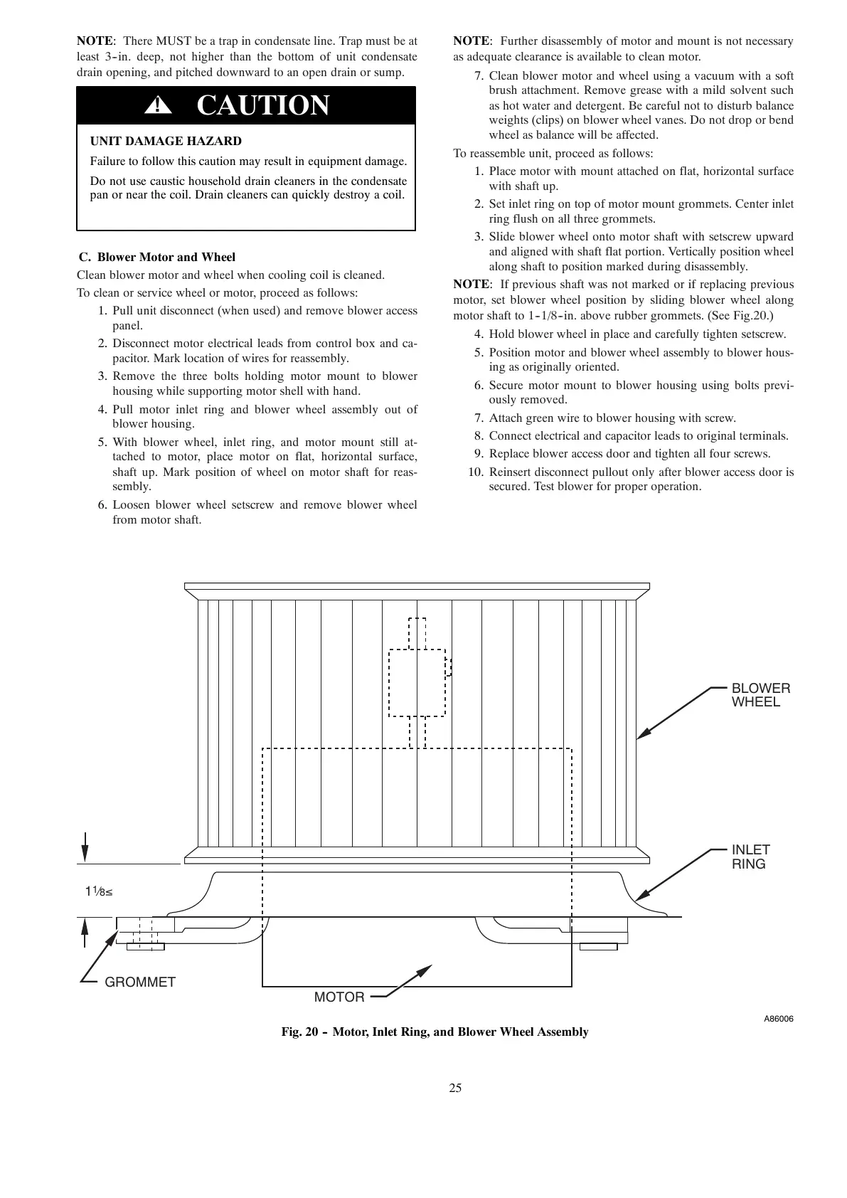
NOTE: If previous shaft was not marked or if replacing previous
motor, set blower wheel position by sliding blower wheel along
motor shaft to 1--1/8--in. above rubber grommets. (See Fig.20.)
4. Hold blower wheel in place and carefully tighten setscrew.
5. Position motor and blower wheel assembly to blower hous-
ing as originally oriented.
6. Secure motor mount to blower housing using bolts previ-
ously removed.
7. Attach green wire to blower housing with screw.
8. Connect electrical and capacitor leads to original terminals.
9. Replace blower access door and tighten all four screws.
10. Reinsert disconnect pullout only after blower access door is
secured. Test blower for proper operation.
GROMMET
BLOWER
WHEEL
INLET
RING
MOTOR
1
1
⁄
8
≤
A86006
Fig. 20 -- Motor, Inlet Ring, and Blower Wheel Assembly