8-27 62-11039
8.16 CHECKING AND REPLACING FILTER-DRIER
To Check F ilter-Drier
Check for a restricted or plugged filter-drier by feeling
the liquid line inlet and outlet connections of the drier
cartridge. If the outlet side feels cooler than the inlet
side, then the filter-drier should be changed.
To Replace F ilter -Drier
a. Pump down the unit per section 8.10.1. Remove
bracket, then replace drier. Tighten inlet side fitting.
b. Slowly open King Valve and purge air through the dri-
er. Tighten drier outlet side fitting.
c. Leak test drier connections.
d. Check refrigerant level.
e. Check unit operation by running Pretrip (Refer to Sec-
tion 3.5).
8.17 ELECTRONIC EXPANSION VALVE (SEE 8.18
FOR INFORMATION ON TXVs FOR REMOTE
COMPARTMENTS)
NOTE
Place unit in Service Mode before performing
the following operations on the unit. Refer to
Section 5.2.3
The electronic expansion valve (EVXV) is an automatic
device which maintains constant superheat of the
refrigerant gas leaving the evaporator regardless of
suction pressure. The valve functions are: (a) automatic
response of refrigerant flow to match the evaporator
load and (b) prevention of liquid refrigerant entering the
compressor. Unless the valve is defective, it seldom
requires any maintenance.
Make sure the EVXV coil is snapped down fully, and the
coil retention tab is properly seated in one of the valve
body dimples.
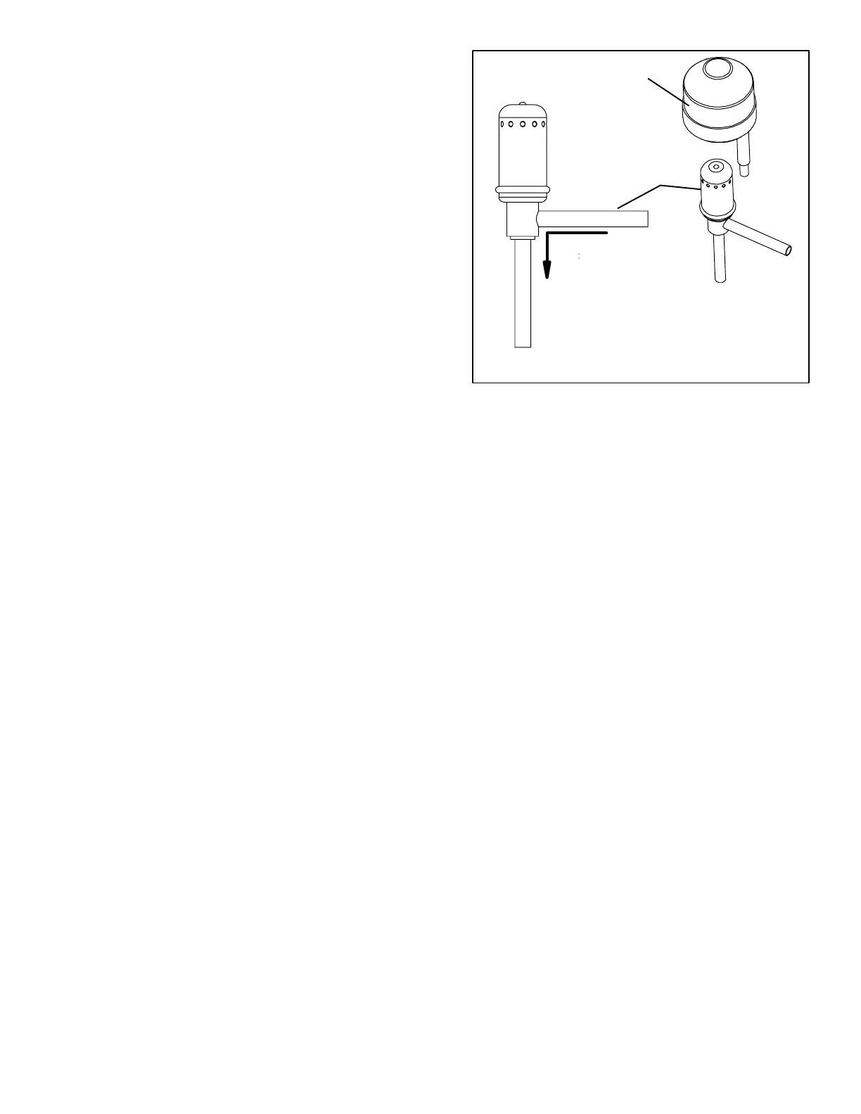
1. Coil
2. Electronic expansion valve
Figure 8--29 Electronic expansion valve
FLOW
DIRECTION
1
2
8.17.1 Replacing Expansion Valve & Screen
a. Pump down the unit by closing the manual shut off
valve (king valve). (Refer to Section 8.10.1.)
b. Remove coil.
c. Use a wet rag to keep valve cool whenever brazing.
Heat inlet, outlet and equalizer connection to valve
body and remove valve. Clean all tube stubs so new
valve fits on easily.
d. Install new valve and screen, with cone of screen
pointing into liquid line at inlet to the valve by revers-
ing steps a.through c.
e. The thermal bulb is located below the center of the
suction line (See Figure 8--31). This area must be
clean to ensure positive bulb contact. Firmly tighten
the straps around the thermal bulb and suction line
and insulate both with Presstite.
f. Evacuate by placing vacuum pump on suction ser-
vice valve.
g. Open king valve and then check refrigerant level.
h. Check superheat. (Refer to Section 2.12)
i.Check unit operation by running Pretrip (Refer to Sec-
tion 3.5).