10 ZP3 Fire Panel User Guide
Panel fascia
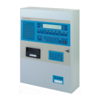
The ZP3 system is operated by means of the controls and indicators on the ZP3
panel Fascia as shown in Figure 3 below. In some systems, the operator controls
the system from a Remote Display Unit and not from the panel fascia. This is
identical to the control panel, but is usually located in some other area, such as a
control room. Effectively the Remote Display Unit is a repeater, which operates in
the same manner as the fire panel.
Figure 3: ZP3 Fire control panel fascia panel layout
LOCAL ZONES
1
9
17
25
33
41
49
2
10
18
26
34
42
50
3
11
19
27
35
43
4
12
20
28
36
44
5
13
21
29
37
45
6
14
22
30
38
46
7
15
23
31
39
47
8
16
24
32
40
48
ZP3 FIRE ALARM SYSTEM
HELP
ACCEPT
MUTE
BUZZER
RESET FIRE FAU LT DISABLED OTHER
SILENCE
ALARMS
SOUND
ALARMS
MORE
VIEW
POINTS
DISABLEDDELAYED PRE-ALM TEST ENABLE
CONTROL
ON
OFF
FAU LTACTIVEPOWER ON
SYSTEMNIGHT
ZONEDAY
POINTMORE TIME
SOUNDERS
REMOTE ALARM
CONTROL OUTPUTS
RESTORE
DISABLED
ALARMS
1
ABC
2
DEF
3
GHI
F1
F2
4
JKL
7
STU
8
VWX
0
[ ]
9
YZ
5
MNO
6
PQR
ESC
Zonal fire
indicators
Help button View devices button
LCD display
Sounder
control buttons
Alarm view buttons
and common
alarm indicators
Access control
Scroll buttons
Day/Night
module
(optional)
Status
indicators
Printer
(optional)
Keypad
Alarm controls and indicators
Alarm view buttons
As shown in Figure 4 below, there are four alarm view buttons located below the
LCD display, directly below the four common alarm indicators, they are:
• Fire
• Fault
• Disabled
• Other
The relevant common alarm indicator illuminates when an alarm is received, and
the zonal details are simultaneously displayed on the LCD display.
Figure 4: Alarm view buttons and common alarm indicators
FIRE FAULT DISABLED OTHER
Buttons
Indicators
 Loading...