ZP3 Fire Panel User Guide 17
Display of alarms
Overview
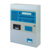
See Figure 9 below. Alarms are indicated both audibly and visibly on the fascia of
the panel (or remote display panel). Audible indication is by means of a built-in
panel buzzer. Visible indication is by means of illuminated LED indicators and
descriptive text on the LCD display.
Figure 9: ZP3 Fire panel controls and indicators
LOCAL ZONES
1
9
17
25
33
41
49
2
10
18
26
34
42
50
3
11
19
27
35
43
4
12
20
28
36
44
5
13
21
29
37
45
6
14
22
30
38
46
7
15
23
31
39
47
8
16
24
32
40
48
ZP3 FIRE ALARM SYSTEM
HELP
ACCEPT
MUTE
BUZZER
RESET FIRE FAU LT DISABLED OTHER
SILENCE
ALARMS
SOUND
ALARMS
MORE
VIEW
POINTS
DISABLEDDELAYED PRE-ALM TEST ENABLE
CONTROL
ON
OFF
FAU LTACTIVEPOWER ON
SYSTEMNIGHT
ZONEDAY
POINTMORE TIME
SOUNDERS
REMOTE ALARM
CONTROL OUTPUTS
RESTORE
DISABLED
ALARMS
1
ABC
2
DEF
3
GHI
F1
F2
4
JKL
7
STU
8
VWX
0
[ ]
9
YZ
5
MNO
6
PQR
ESC
Zonal fire
indicators
Help button View devices button
LCD display
Sounder
control buttons
Alarm view buttons
and common
alarm indicators
Access control
Scroll buttons
Day/Night
module
(optional)
Status
indicators
Printer
(optional)
Keypad
Fire alarms
Fire alarms are shown by means of the common Fire LED, the Zone LEDs, and
the LCD display. The operation of functions arising from the fire alarm, such as
sounders, control outputs, or remote manned centre alarms, is shown by means
of the status indicators.
Fault alarms
Fault alarms are shown by means of the common Fault LED and the LCD
display. The operation of functions arising from the fault alarm, such as control
outputs, or remote manned centre alarms, is shown by means of illuminated
status indicators.
 Loading...