19 // GB
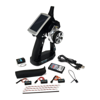
The Switch 4/15P. switching module allows you to switch lights and other consumers (e.g. motors, pumps, relays) directly via the channel of an RC remote control.
There are 4 outputs available on the switching module, which can be loaded with a current of up to 4 A. The total current of all outputs must not exceed 10 A.
The states of the 4 outputs are indicated by coloured LEDs. This makes it easy to see which of the 4 outputs is switched on.
When the Switch 4/15P. is delivered, mode 1 is preset.
For modes 3, 4, 7, 10 and 14, a proportional encoder (joystick, slider, rotary control) is required on the transmitter, as the Switch 4/15P. must evaluate proportional (stepless) signals here.
For all other modes, a 3-position switch on the transmitter is sufficient to control the outputs. Proportional encoders can also be used here.
The Switch 4/15P. has 15 different switching modes that can be selected via setup:
CONTENTS
Description ......................................................................................................................................19
Technical specifications ................................................................................................................ 20
Connection diagram ...................................................................................................................... 21
Division of the RC channel into ranges .......................................................................................... 21
Setup – Switching mode selection ............................................................................................... 22
Change mode settings with internal digital pot .......................................................................... 23
Mode 1: 4-way memory brief / long ............................................................................................. 23
Mode 2: 2-way memory brief / 2-way momentary long ..............................................................24
Mode 3: 4-way memory over ranges A, B, C, D ..............................................................................24
Mode 4: 4-way momentary over ranges A, B, C, D ........................................................................ 25
Mode 5: 4-way memory via counting mode (EKMFA - A) ............................................................. 25
Mode 6: 4-way memory via counting mode (EKMFA - D) ............................................................. 26
Mode 7: Impulse / activation on movement ................................................................................. 26
Mode 8: 4-way light switch individual (step switch) ................................................................... 27
Mode 9: 4-way light switch combined.......................................................................................... 27
Mode 10: Blinkers (steering), hazard lights, lights 1+2 ...............................................................28
Mode 11: Indicator (memory), hazard lights, lights 1+2 ............................................................. 29
Mode 12: Indicators (automatic shutdown), hazard lights, light 1+2 .........................................30
Mode 13: Indicator (memory), light 1, light 2 ................................................................................31
Mode 14: Brake light, light, reversing light .................................................................................. 32
Mode 15: Flasher, running light .................................................................................................... 33
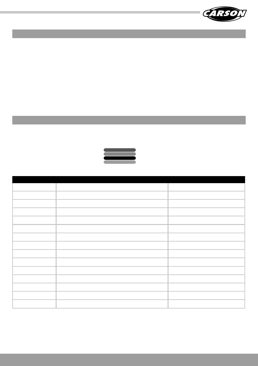
DESCRIPTION
OUTPUT 1 GREEN
OUTPUT 3 BLUE
OUTPUT 2 RED
OUTPUT 4 YELLOW
MODE FUNCTION ENCODER ON THE TRANSMITTER
1 4-way memory brief / long Switch
2 2-way memory brief / 2-way momentary long Switch
3 4-way memory over ranges A, B, C, D Proportional
4 4-way momentary over ranges A, B, C, D Proportional
5 4-way memory via counting mode (EKMFA - A) Switch
6 4-way memory via counting mode (EKMFA - D) Switch
7 Impulse during movement Proportional
8 4-way light switch individual (step switch) Switch
9 4-way light switch combined Switch
10 Blinkers (steering), hazard lights, lights 1+2 Proportional (steering channel)
11 Indicator (memory), hazard lights, lights 1+2 Switch
12 Indicator (automatic switch-off), hazard lights, light 1+2 Switch
13 Indicator (memory), light 1, light 2 Switch
14 Brake light, light, reversing light Proportional (throttle channel)
15 Flasher, running light Switch