GB // 26
Ranges A, B and C are not evaluated in this mode.
As this mode only requires a „half“ RC channel (range D), a second Switch 4/15P. could be connected to the same channel via a Y-cable, which would be set to mode 5 and evaluate range A. Up to 8
outputs can be switched via one channel (4 x range A with the first
Switch 4/15P. and 4 x range D with the second Switch 4/15P.).
If there is no more change, the outputs switch off again. Consequently, the output only switches on for as long as there is movement of the encoder.
The sensitivity of the change monitoring can be adjusted with the internal “digital potentiometer” (see page 23). The smaller the set value of the „digital potentiometer“, the more sensitive the
change monitoring. With larger „digital potentiometer“ values, the encoder must be moved more to achieve output switching.
The outputs of the Switch 4/15P. can also be combined by simple parallel switching, for example to generate an impulse, irrespective of the direction in which or range in which the movement takes
place.
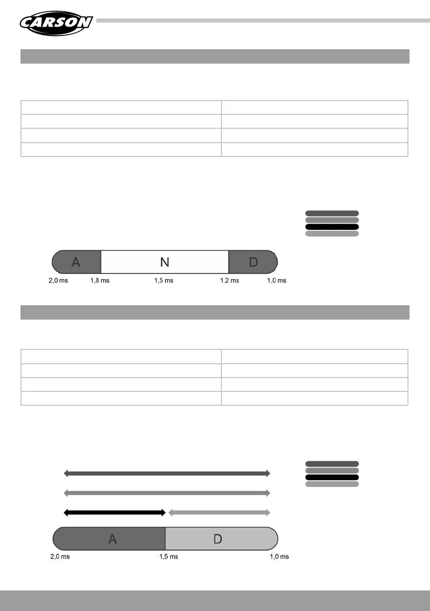
1 x in range D: Output 1 switches on or off (memory)
2 x in range D: Output 2 switches on or off (memory)
3 x in range D: Output 3 switches on or off (memory)
4 x in range D: Output 4 switches on or off (memory)
Movement to the left: Output 1 switches on
Movement to the right: Output 2 switches on
Movement in range A: Output 3 switches on
Movement in range D: Output 4 switches on
This mode works according to the counting principle (also known as EKMFA in our sound modules). Each time the encoder is moved to range D, a counter is incremented. If there are no further
counting pulses for 1 second, the output that corresponds to the counter status is switched on or off. The counter is then reset to 0.
The max. counter status is 4. For example, if the counter status becomes 5, output 4 is still switched.
A proportional encoder is required on the transmitter for this mode, as a change in the proportional signal is evaluated here.
The 4 outputs switch on if the encoder signal changes as follows:
MODE 6: 4-WAY MEMORY VIA COUNTING MODE (EKMFA - D)
MODE 7: IMPULSE / ACTIVATION ON MOVEMENT
Output 1
Output 2
Output 3
Output 4
Output 4Output 3
Output 2
Output 1
OUTPUT 1 GREEN
OUTPUT 3 BLUE
OUTPUT 2 RED
OUTPUT 4 YELLOW
OUTPUT 1 GREEN
OUTPUT 3 BLUE
OUTPUT 2 RED
OUTPUT 4 YELLOW