GB // 30
Here, the indicator is not controlled via the steering, but via a separate channel, with a 3-position switch. In contrast to mode 11, however, the indicators are automatically switched off again after a
configurable number of flashes.
The flash frequency of the indicator is set using the „digital potentiometer“ (see page 23):
The left indicator, right indicator and hazard lights automatically switch one another off as soon as they are activated.
In addition to the indicators on the right and left, 2 further outputs for 2 lights, as well as the hazard lights (right and left indicators at the same time) can be switched.
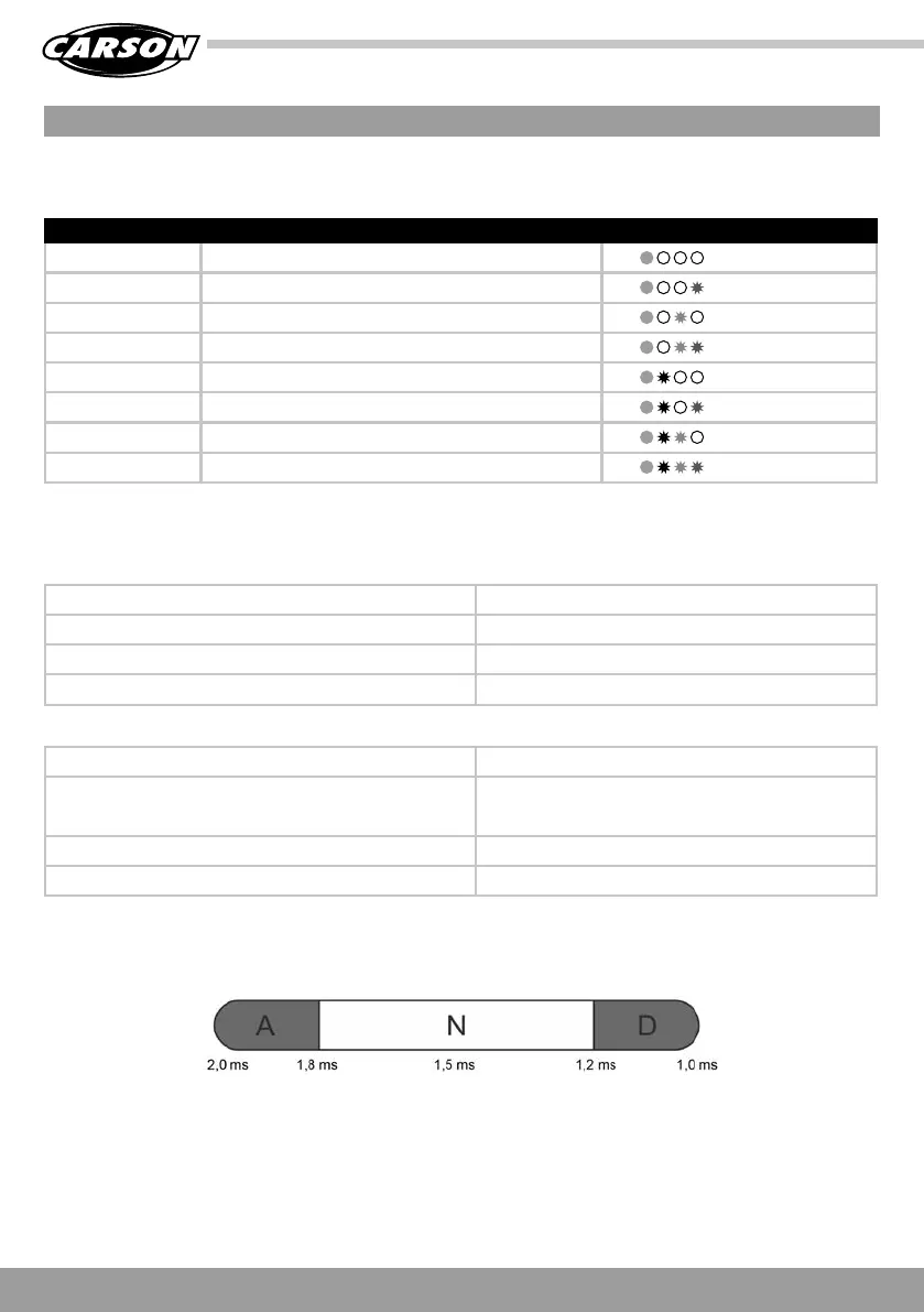
The intermediate ranges B and C are not evaluated in this mode.
Output 1: Left indicator
Output 2: Light 1
Output 3: Light 2
Output 4: Right indicator
Brief in range A: Switches left indicator on (memory)
Long in range A: 1 x switches light 1 on (memory)
2 x switches light 2 on (memory)
3 x switches light 1 and light 2 off again
Long in range D: Switches hazard warning lights on or off (memory)
Brief in range D: Switches right indicator on (memory)
Assignment of the outputs:
Function control:
MODE 12: INDICATORS (AUTOMATIC SHUTDOWN), HAZARD LIGHTS, LIGHT 1+2
DIGITAL POTENTIOMETER SHUTDOWN AFTER X FLASHES LEDs
0 2x
1 3x
2 4x
3 5x
4 6x
5 7x
6 8x
7 9x
Left indicator
Light 1 + Light 2
Right indicator
Hazard lights