10
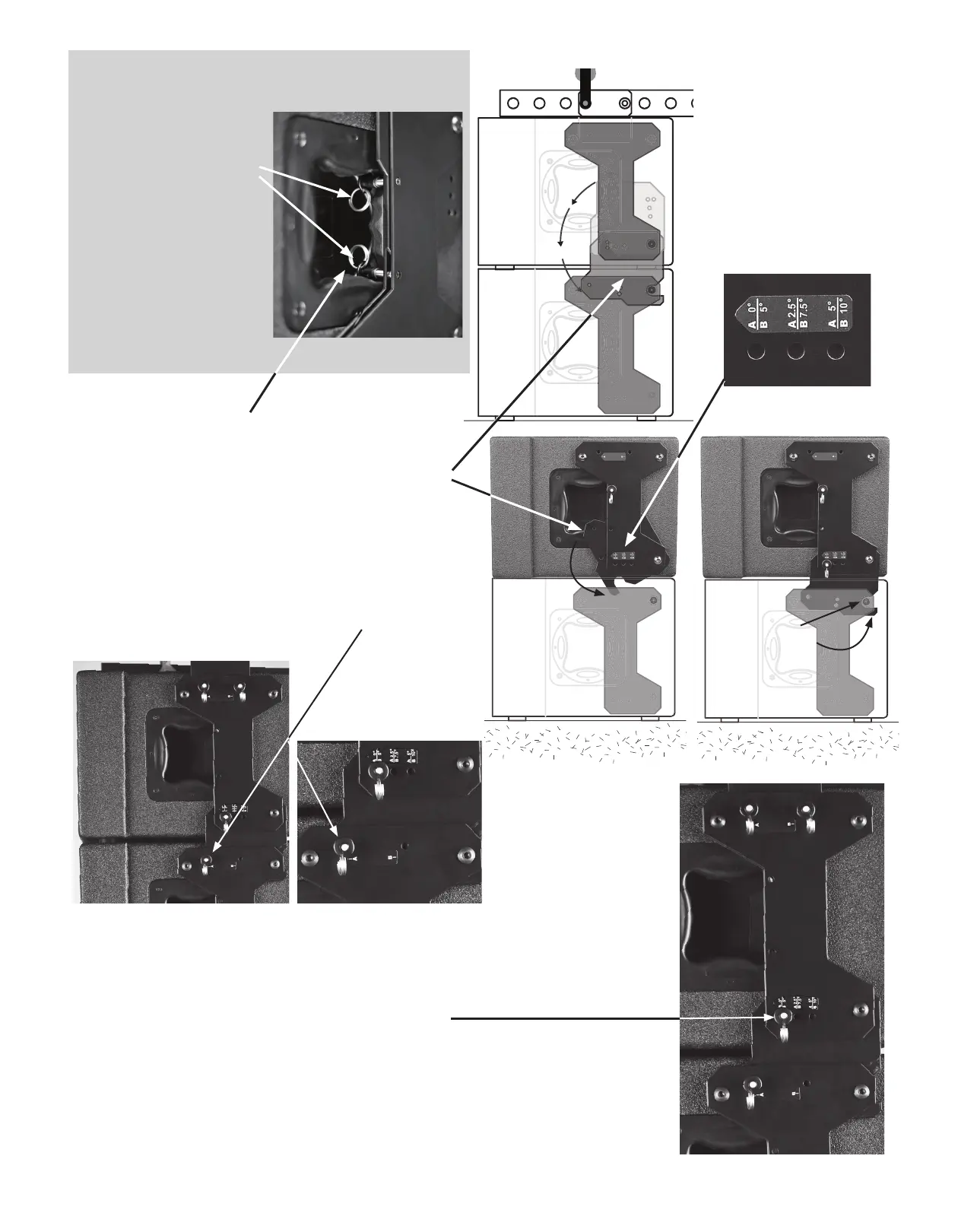
Step 5
Remove the lower quick-release pin from the han-
dle storage location to release the adjustment plate.
Allow the adjustment plate to swing down between
the two side plates on the lower enclosure. Adjust
enclosures to allow adjustment plate to capture the
lower enclosure with hook on adjustment plate.
When the adjustment plate is fully in place, the “A”
location pin can be inserted. Repeat on opposite
side of array enclosure.
Step 6
Push the second quick-release pin into forward
hole labeled (A 0˚) on the upper enclosure. Repeat
on opposite side of array enclosure. This 0 degree
position is used for a straight Line-Array. This is
also storage and transport position when using the
DB3210 dolly board.
e quick-release pins
can be stored in the
handles on the inside
of the SureFly hardware
plates on each side of
the array module. is
keeps them from being
misplaced or damaged
during transport and
holds the inner adjust-
ment plate from swing-
ing down.
Pin Storage
GROUND
Attach to motor hoist
A
d
j
u
s
t
m
e
n
t
p
l
a
t
e
s
w
i
n
g
s
d
o
w
n
Adjustment plate
hook captures
lower enclosure
close up view
 Loading...