Do you have a question about the CAS BI Series and is the answer not in the manual?
Appreciation for purchasing BI-SERIES and recommendation to read the manual.
Important warnings and precautions for safe operation and handling of the indicator.
Highlights key features such as battery use, operation ease, and resolution.
Lists core functionalities including averaging, counting, and comparing.
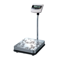
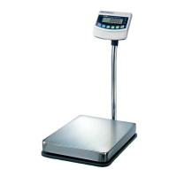
Detailed technical specifications for different BI-SERIES models.
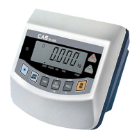
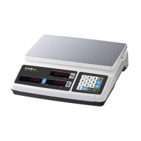
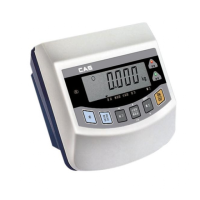
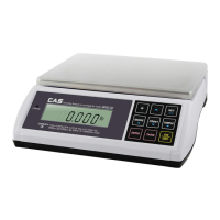
Identifies and describes the key components of the weighing indicator.
Describes the functions of the keys on the weighing indicator.
Used to power the weighing indicator ON or OFF.
Used for rezeroing or entering system mode.
Used for tare weighing operations.
Used to turn the backlight ON or OFF.
Displays NET/GROSS weight or weighs moving objects.
Displays the unit weight for approximately 5 seconds.
Displays the current weight for approximately 5 seconds.
Displays weight after weighing.
Determines and displays high, normal, or low value.
Displays quantity by setting unit or sample weight.
Displays quantity after discrimination by setting High/Low.
Procedure for converting between different operating modes.
Sets the inputted value to '0'.
Increases the first place of value by one.
Moves the inputted value to the left by one place.
Inputs a decimal point.
Completes the input process.
Steps to convert to the simple weighing mode.
Procedure for High/Low comparing mode without resetting.
Procedure for High/Low comparing mode with resetting.
Procedure for count mode without setting unit/sample weight.
Procedure for setting unit weight in count mode.
Procedure for setting unit weight using sample count.
Procedure for count comparing mode without setting High/Low quantity.
Procedure for setting High/Low quantity in count comparing mode.
Resets the zero point of the weighing indicator.
Subtracts the weight of a container or tare object.
Displays the total weight including tare.
Displays the weight of the object only.
Procedure to remove the saved tare weight.
Automatically holds the weight when it becomes stable.
How to release the auto hold function.
Manually holds the weight by pressing the 'Hold' key.
Steps to enter the conversion mode menu.
Explanation of keys used within conversion mode.
Lists available conversion menus: Auto power OFF and RS-232C.
Configures automatic power off to save battery.
Configures RS-232C communication parameters.
How to connect the indicator to a computer via RS-232C.
Specifies the baud rate for RS-232C communication.
Specifies data bits, stop bits, and parity for RS-232C.
Specifies ASCII as the data encoding format.
Details the total byte structure of transmitted data.
Explains the bit mapping for indicator lamp status.
Indicates the unit of weight in the transmitted data.
Details the 8-byte format for transmitting weight data.
Example BASIC program for data transmission/reception.
Example C program for data transmission/reception.
Connecting the loadcell to the indicator's back panel.
Diagram illustrating loadcell and connector connection.
Details loadcell output rate and recommended resolution.
Provides a color-coding guide for loadcell wires by manufacturer.
Preparing batteries for use after storage.
Checking the power switch position for operation.
Steps to power on the indicator using the front panel key.
Diagram showing the location of power switch and connectors.
Procedure to turn off the indicator.
Instructions for powering off for long-term storage.
When to replace or charge batteries.
Instructions for using and replacing standard batteries.
How to insert general batteries checking polarity.
Preparing to use rechargeable batteries.
Connecting the adapter for charging rechargeable batteries.
Indicates the RED power lamp is ON when adapter is connected.
Indicates the RED charge lamp is ON during charging.
Indicates the GREEN charge lamp is ON upon charging completion.
Approximate time required for full battery charge.
Provides estimated battery usage periods under different conditions.
Steps to access the test function menu.
Lists the available test functions (LCD, A/D, Key, RS-232C).
Tests the functionality of the liquid crystal display.
Tests the analog-to-digital conversion process.
Tests the responsiveness and codes of the keys.
Tests the communication link via RS-232C port.
Procedure to start and run the LCD display test.
Procedure to start and run the A/D conversion test.
Table mapping indicator keys to their respective codes.
Procedure to test RS-232C communication link.
Table showing ASCII codes for characters.
Procedure to test loadcell output voltage.
Steps to enter the calibration mode.
Lists calibration options: capacity, division, span, zero, span.
Sets the maximum weight capacity for the scale.
Sets the smallest measurable weight unit (division).
Sets the weight used for span calibration.
Performs automatic zero calibration.
Performs automatic span calibration with a test weight.
Explains how to input numerical values during calibration.
Sets the maximum weight capacity for the scale.
Sets the smallest measurable weight unit (division).
Sets the weight used for span calibration.
Performs automatic zero calibration.
Performs automatic span calibration with a test weight.
Steps for sealing the indicator after calibration.
Action to open the top cover for sealing.
Covering the CAL switch with a sealing plate and bolts.
Connecting the sealing wire and compressing the lead.
Diagram showing wall mounting dimensions.
Diagram showing fixed bracket dimensions.
Descriptions and management for errors during weighing.
Cause and management for initialization failure.
Cause and management for loadcell or A/D conversion fault.
Cause and management for calibration data loss.
Cause and management for printer connection issues.
Cause for current weight exceeding zero range.
Cause and management for tare weight exceeding maximum capacity.
Initial zero range exceeds 10% of maximum capacity.
Initial zero range exceeds 10% of maximum capacity.
Check the loadcell state.
Too heavy object exceeds maximum capacity.
Too heavy object exceeds maximum capacity.
Do not exceed maximum capacity; check/replace loadcell.
Descriptions and management for errors during calibration.
Span weight set below 10% of max capacity.
Span weight set exceeds 100% of max capacity.
Resolution set too high compared to loadcell output.
Zero value is too high.
Zero value is too low.
Zero value is too low.
Check that the platform is empty.
The weight reading trembles.
The weight reading trembles.
Check loadcell connector connection.
Descriptions and management for errors in count mode.
Count unit weight and sample weight set too high.
Count unit weight and sample weight set too low.
| Display | LCD |
|---|---|
| Units | g, oz |
| Functions | Counting |
| Material | Stainless Steel |
| Readability | 0.001g |
| Interface | RS-232 |