SECTION 2 - CONTROLS, INSTRUMENTS AND OPERATION
2ï27
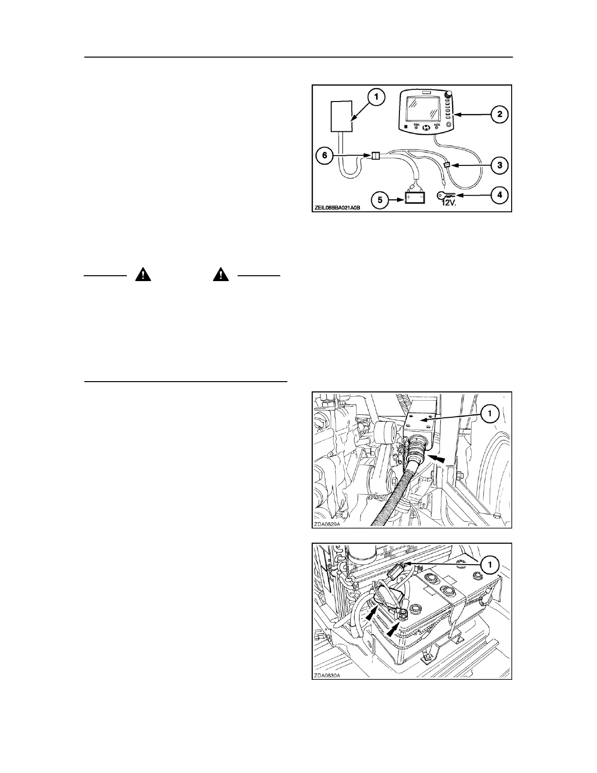
MONITOR INSTALLATION
NOTE: A choice of two monitors are available for the big
balers, connection is the same for both options. This
installation is for non ISOBUS tractors only, ISOBUS
tractors have connections already fitted.
1. Baler controller and fuse box
2. Monitor.
3. Monitor connector
4. Key start: 12 V after tractor contact (orange wires
to be twisted together and connected at the same
point).
44
5. Battery
6. Break-away connector
WARNING
Route and secure all wiring looms away from sharp edges
and vibrating or rotating parts. Make sure the wiring loom
does not rub the PTO and has enough slack to permit
sharp turns.
The red wire in the power cable must always be connected
to the positive (+) battery terminal and the black wire
connected to the negative (-) battery terminal. Failure to
do so will result in damage to the wiring loom.
Install the break-away connector support (1) at a
central position at the rear of the tractor.
Position the support so that the female socket points
rearward, in line with the drive direction of the tractor.
Attach the male plug on the baler wiring loom to the
break-away connector (Fig. 45).
Route the wiring loom (from the break-away connector
with integrated circuit breaker) towards the battery
terminals.
Connect the red wire (1) in the power cable to the 45
positive (+) battery terminal and all black and blue wires
to the negative (-) battery terminal (Fig. 46).
ATTENTION: Failure to follow these instructions will result
in damage to the wiring looms and to the electronic
devices.