Do you have a question about the Casio PX-575R and is the answer not in the manual?
Initial settings and procedures to start the diagnostic program.
Checks for CPU RAM, DSP RAM, ROM, SR ROM, ZX ROM, and Flash Memory.
Procedures for checking switches, the bender dial, and pedals.
Procedures for checking LCD, LEDs, and SD card functionality.
Schematic diagram for the Main PCB M421-MDA1 (Part 1/2).
Schematic diagram for the Main PCB M421-MDA1 (Part 2/2).
Schematic diagram for all Console PCBs (CNA1-CNA8).
Schematic diagram for the Jack PCB M421-PSB1.
Detailed view of the Jack PCB M421-PSB1 schematic.
Schematic diagrams for Jack PCB M421-PSC1 and SD Card PCB M421-SDA1.
| Category | Digital Piano |
|---|---|
| Recording | Real-time recording, playback |
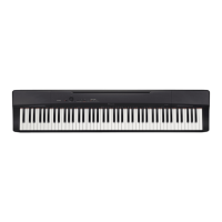
| Amplifier Output | 8W + 8W |
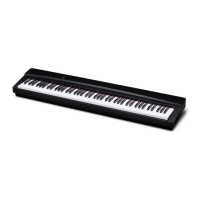
| Keyboard | 88 keys |
| Key Action | Scaled Hammer Action |
| Touch Sensitivity | 3 levels, off |
| Digital Effects | Reverb, Chorus |
| Metronome | Yes |
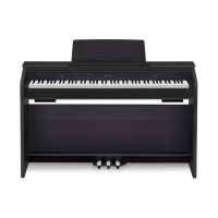
| Speakers | 12 cm x 2 |
| Terminals | USB |
| Connections | USB |
| Power Supply | AC adaptor |