– 2 –
1-3. INTERFACE SPECIFICATION
1-3-1. RS-232C SPECIFI CATION
Data transmission: Serial. EIA RS232C compliant
Synchronization: Asynchronous
Handshaking: DTR/DSR or XON/XOFF control (*)
Signal levels: MARK = -3 to -15V: Logic “1”/OFF
SPACE = +3 to +15V: Logic “0”/ON
Baud rate: 4800, 9600, 19200, 38400 bps (*)
Data word length: 8 bits, 7 bits (*)
Parity Settings: None, even, odd (*)
Stop bits: 1 or more
Connector (printer side): Male DSUB-9 pin connector
Notes: *The data word length, baud rate, and parity depend on the DIP switch settings. (Refer to
5.SETTING & CHECKING THE DIP SWITCHES.)
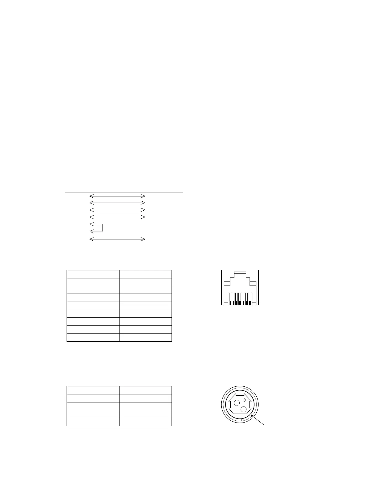
1-3-2. RS-232C INTERFACE CONNECTION EXAMPLE
HOST SIDE PRINTER SIDE
(DTE ex.8251) (Pin No.)
TxD RxD (2)
RxD TxD (3)
DTR DSR (6)
DSR DTR (4)
RTS
CTS
GND GND (5)
1-3-3. LAN CONNECTOR
PIN DESCRIPTION
1 TX+
2 TX-
3 RX+
4 Isolated GND
5 Isolated GND
6 RX-
7 Isolated GND
8 Isolated GND
1-3-4. POWER SUPPLY CONNECTOR
The connector is connected the printer to an external power source.
CONNECTOR MODEL:
PIN SIGNAL
1 +24V
2 GND
3 NC
shell FG