EasyManua.ls Logo

Cassese CS 940 - Page 18

Cassese CS 940
72 pages
Print Icon
To Next Page IconTo Next Page
To Previous Page IconTo Previous Page
Loading...
USER & PARTS MANUAL
CS940
18
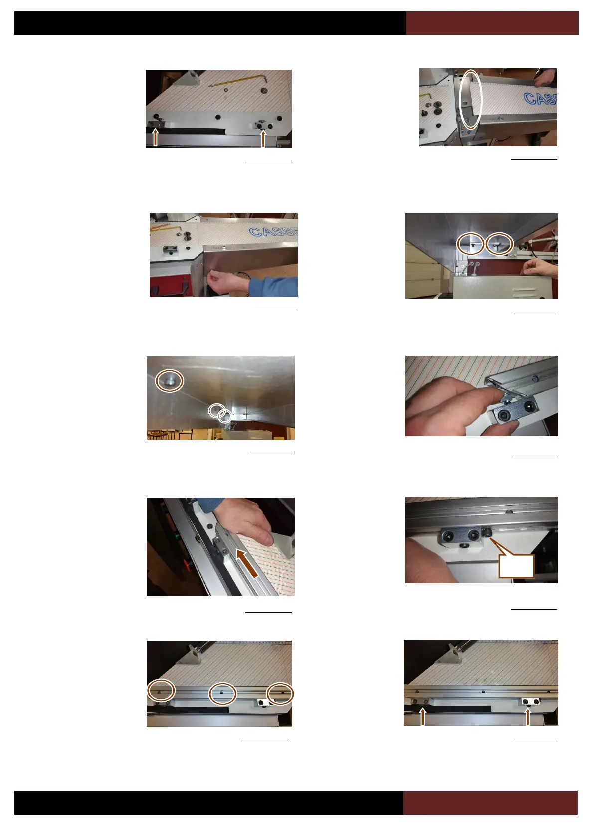
Unlock the 2
horizontal screws of 4
turns (see picture
opposite). If needed
use the flat span of
10mm to hold the nut
at the extremity of the
screw.
Figure 4-11
Figure 4-16
Figure 4-17
Figure 4-19
Figure 4-20
Start to install the right
arm (8), taking care of
not damaging the
extremity of the scale.
Figure 4-12
With the help of a
second person holding
the arm, install back
the (V1) screw that
was dismounted in
Figure 4-12. Do not
block the screw yet.
Figure 4-13
Still with the help of
the second person to
hold the arm, put back
the screws (V2) and
(V3), do not block
them.
Figure 4-14
Unlock the 3 screws
under the right arm of
4 turns.
Slide the right arm
profile (6) in the
screw as shown in
the picture opposite.
Figure 4-15
Slide the profile to
center of the saw,
paying attention that
the (ULF) screws are
sliding gently in the
bottom track of the
profile.
Lock the 3 screws
(ULF).
Figure 4-18
Slide the profile until
the stop nut (B) is
reached.
Lock the 2 horizontal
screws back.
B

Table of Contents