4
Table 2 shows the capacity values that are recommended for
fuses in the line with delays.
Table 2
Model
MATRIX 420-4200
E / E-MG
Input power @ I
2
Max kVA 17,4
Delayed fuse (I
2
@ 100%) A 16
Duty cycle @ 40% (40°C) A 420
Mains cable
Length
Section
m
mm
2
4
2,5
Ground cable
Section mm
2
50
NOTE: Any extensions to the power cable must be of a suita-
ble diameter, and absolutely not of a smaller diameter than the
special cable supplied with the machine.
Instructions for use
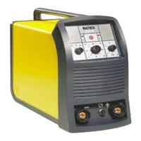
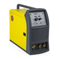
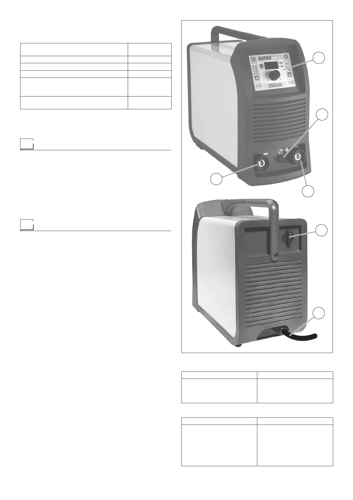
COMMAND AND CONTROL UNITS (Fig. A)
Pos. 1 MX command and control panel. For detailed infor-
mation on the control panel, see the instruction man-
ual enclosed.
Pos. 2 6 pole remote control connector.
Pos. 3 Positive pole quick connection.
Pos. 4 Negative pole quick connection.
Pos. 5 Power supply switch. In the “O” position the welder
is off.
Pos. 6 Mains cable.
Electrode welding (MMA)
Electrode welding is used for welding most metals (various
types of steels, etc.) using rutilic, basic, and cellulosic elec
-
trodes with diameters from 1.6 mm to 6.0 mm.
1) Connecting the welding cables (Fig. B):
Disconnect the machine from the mains power supply and
connect the welding cables to the output terminals (Positive
and Negative) of the welding machine, attaching them to
the clamp and ground with the polarity specified for the type
of electrode being used (Fig.B). Always follow the electrode
manufacturer’s instructions. The welding cables must be
as short as possible, they must be near to one another, po-
sitioned at or near floor level. Do not touch the electrode
clamp and the ground clamp simultaneously.
2) Switch the welding machine on by moving the power sup-
ply switch to I (Pos. 5, Fig. A).
3) Make the adjustments and select the parameters on the
control panel (for further information see the MX control
panel manual).
4) Carry out welding by moving the torch to the workpiece.
Strike the arc (press the electrode quickly against the met-
al and then lift it) to melt the electrode, the coating of which
forms a protective residue. Then continue welding by mov-
ing the electrode from left to right, inclining it by about 60°
compared with the metal in relation to the direction of weld-
ing.
PART TO BE WELDED
The part to be welded must always be connected to ground
in order to reduce electromagnetic emission. Much attention
must be afforded so that the ground connection of the part to
be welded does not increase the risk of accident to the user or
the risk of damage to other electric equipment. When it is nec-
essary to connect the part to be welded to ground, you should
make a direct connection between the part and the ground
shaft. In those countries in which such a connection is not al-
lowed, connect the part to be welded to ground using suitable
capacitors, in compliance with the national regulations.
1
2
4
5
6
3
FIG. A
Table 3
WELDING THICKNESS (mm) Ø ELECTRODE (mm)
1,5 ÷ 3
3 ÷ 5
5 ÷ 12
≥ 12
2
2,5
3,2
4
Table 4
Ø ELECTRODE (mm) CURRENT (A)
1,6
2
2,5
3,2
4
5
6
30 ÷ 60
40 ÷ 75
60 ÷ 110
95 ÷ 140
140 ÷ 190
190 ÷ 240
220 ÷ 330