7
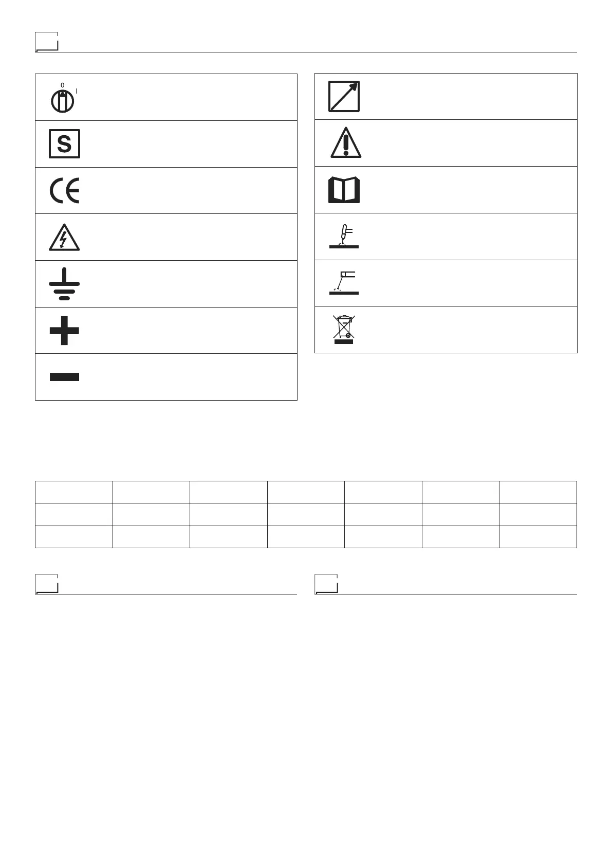
Meaning of graphic symbols on machine
Power supply switch
System for use in environments with in-
creased risk of electroshock
Product suitable for free circulation in the Eu-
ropean Community
Dangerous voltage
Grounding
Positive pole snap-in connector
Negative pole snap-in connector
Remote control socket
Warning!
Before using the equipment you should care-
fully read the instructions included in this man-
ual
TIG welding
MMA welding
Special disposal
Key to the electrical diagram
•1 EMC filter •2 Remote control socket •3 Protection capacitor •4 Secund-
ary diodes •5 Power supply switch •6 Secondary inductor •7 Primary upper
IGBT •8 Lower primary IGBT •9 Fan motor •10 Main primary transform-
er (start) •11 Main primary transformer (end) •12 Remote current poten-
tiometer •13 Primary rectifier •14 Capacitors PCB (MATRIX 420 E-MG)
•15 Booster board •16 Digital interface PCB •17 Inverter PCB •18 Auxilia-
ry transformer •19 Current transducer •20 Thermostat on the secondary
heatsink •21 Transformer
Colour key
Ar Orange
Az Sky Blue
Bc White
Bl Blue
GV Yellow Green
Mr Brown
Nr Black
Ro Pink
Rs Red
Vd Green
Vl Violet
•1 •2 •3 •4 •5 •6 •7
3PH-EMC CCD Cp D1-2-3-4-5-6 IL L MIH
•8 •9 •10 •11 •12 •13 •14
MIL MV P1 P2 PD RP S-C4 LINK
•15 •16 •17 •18 •19 •20 •21
S-DOUBLER S-INT DIG S-INV TA TC TH2 TP