5
WELDING PARAMETERS
Table 3 shows some general indications for the choice of elec-
trode, based on the thickness of the parts to be welded. The
values of current to use are shown in the table with the respec-
tive electrodes for the welding of common steels and low-grade
alloys. These data have no absolute value and are indicative
data only. For a precise choice follow the instructions provided
by the electrode manufacturer.
The current to be used depends on the welding positions and
the type of joint, and it increases according to the thickness and
dimensions of the part.
The current intensity to be used for the different types of weld-
ing, within the field of regulation shown in table 4 is:
• High for plane, frontal plane and vertical upwards welding.
• Medium for overhead welding.
•
Low for vertical downwards welding and for joining small pre-
heated pieces.
A fairly approximate indication of the average current to use in
the welding of electrodes for ordinary steel is given by the fol-
lowing formula:
I = 50 × (Øe - 1)
Where:
I = intensity of the welding current
Øe = electrode diameter
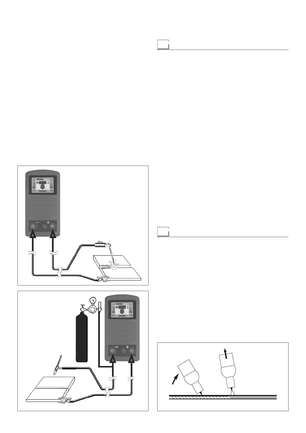
FIG. B
FIG. C
Example:
For electrode diameter 4 mm
I = 50 × (4 - 1) = 50 × 3 = 150A
TIG welding
TIG welding melts the metal of the workpiece, using an arc
struck by a tungsten electrode. The fusion bath and the elec-
trode are protected by gas (Argon). This type of welding is used
to weld thin sheet metal or when elevated quality is required.
1) Connecting the welding cables (Fig. C):
•
Connect one end of the gas hose to the gas connecter
on the TIG torch and the other end to the Argon cylin-
der and open it.
• With the machine switched off:
-
Connect the ground cable to the snap-on connector
marked + (positive).
-
Connect the relative ground clamp to the workpiece or
to the workpiece support in an area free of rust, paint,
grease, etc..
-
Connect the TIG torch power cable to the snap-on con
-
nector marked - (negative).
2) Switch the welding machine on by moving the power sup-
ply switch to I (Pos. 5, Fig. A).
3) Make the adjustments and select the parameters on the
control panel (for further information see the MX control
panel manual).
4) Open the gas cylinder and regulate the flow by adjusting
the valve on the TIG torch by hand.
5) Ignite the electric arc by contact, using a decisive, quick
movement at the welding current set (“Lift” type ignition -
Fig. D).
To end welding:
•
Lift the torch slowly, at a certain point the welding current
decreases, and then stop.
•
The welding machine follows an automatic down slope
along with extinguishing of the arc.
6) When you have finished welding remember to shut the
valve on the torch and the gas cylinder.
Maintenance
ATTENTION: Before carrying out any inspection of the inside
of the generator, disconnect the system from the supply.
SPARE PARTS
Original spare parts have been specially designed for our
equipment. The use of non-original spare parts may cause
variations in performance or reduce the foreseen level of safety.
We decline all responsibility for the use of non-original spare
parts.
2000HA802000HA81
FIG. D
2000HA86