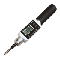
The CEDAR Torque Tester, DID & DIW Series, is a precision instrument designed for measuring torque in various applications, including torque drivers and torque wrenches. This operation manual provides comprehensive details for safe, efficient, and accurate use of the device.
Function Description
The CEDAR Torque Tester offers multiple measurement modes to suit different needs:
- P-P (Peak to Peak) Mode: This mode continuously displays the maximum torque value applied during measurement. It is generally used for standard torque measurements where the peak load is of interest. The device holds loads greater than 20 digits, ensuring accurate capture of peak values.
- P-D (Peak-Down) Mode: In this mode, the device displays a torque value when the applied load torque transitions from a rise to a descent. This is particularly useful for measuring torque wrenches or drivers where the "breakaway" or "click" torque is critical. The downward width to judge the peak-down can be adjusted, allowing for tailored measurements. Like P-P mode, it operates with loads greater than 20 digits.
- C (Real-time Output) Mode: This mode outputs load torque values approximately every 1/160th of a second, with a possible change interval of 1/12th of a second. It is ideal for creating torque curves or examining screw bundles, providing continuous data for analysis.
- T-R (Track) Mode: Primarily used for calibration, this mode displays the load torque value concerning a detector as it is applied, without any additional processing or display features.
The device also incorporates a convenient function for setting maximum and minimum values, enabling pass/fail judgments based on user-defined limits. Green and red LEDs provide visual feedback for "GOOD" (within limits) and "NG" (out of limits) results, respectively, often accompanied by an audible buzzer.
Important Technical Specifications
The CEDAR Torque Tester series includes models DID-05, DID-4, DIW-15, DIW-20, DIW-75, and DIW-120, each with specific measurement ranges and applications.
Measurement Ranges:
- DID-05: 2.0-500 mN·m
- DID-4: 0.020-4 N·m, 0.020-5 kgf·cm, 0.020-4.5 lbf·in
- DIW-15: 0.20-15 N·m, 2.0-150 kgf·cm, 2.0-130 lbf·in
- DIW-20: 0.20-20 N·m, 2.0-200 kgf·cm, 2.0-174 lbf·in
- DIW-75: 0.20-75 N·m, 2.0-750 kgf·cm, 2.0-651 lbf·in
- DIW-120: 2.0-120 N·m, 20-1200 kgf·cm, 20-1040 lbf·in
Accuracy:
- All models boast an accuracy of ±0.5% (499 digits or less ±3 digits for DID-05, DID-4, DIW-15, DIW-20, DIW-75, and 199 digits or less ±3 digits for DIW-120).
Display:
- The device features a 4-figure digital LCD display.
- Measurement direction: CW-CCW (right and left).
Judging Function:
- High-low limits judging function: High and low values can be set for measurement within limits.
- Results judgment: Performed in P-P mode, confirmed by lamp lighting or buzzer.
Data Management:
- Maximum, minimum, and average values are displayed for up to 800 data points.
- Real-time output: Load torque value outputted approximately every 1/160 second.
- Data memory: Stores up to 800 measured values.
- Data output: ASCII format (baud rate 19200) via USB (B type).
- Automatic clear time: Indication automatically clears in 0.1-3.0 seconds (0.5-second interval). Manual zero clearance is possible with a 0.0-second setup.
Power Source:
- Ni-MH battery (1.2V x 4 cells, 800mAh for DID-05, 650mAh for other models).
- Charge life: 300 times or more.
- Auto power OFF: After 10 minutes of inactivity.
- Charge time: Approximately 3 hours for about 12 hours of consecutive use.
- Important: Measurement cannot be performed while charging. The plug must be pulled out during measurement.
Accessories:
- Exclusive case
- AC/DC adaptor
- Calibration result, certification on calibration, traceability system figure.
- Bits/sockets vary by model: DID-05 uses Bit φ4, DID-4 uses Bit 6.35HEX, DIW-15/20/75/120 use one-way sockets.
Usage Features
Preparation of Measurement:
- Bit/Socket Attachment: Attach the appropriate bit and socket for the task.
- Zero Adjustment: Ensure the display reads zero. If not, perform zero adjustment by pushing the CLEAR button. The device performs automatic zero adjustment upon power-on and mode change, but manual adjustment is available if needed.
- Mode and Function Setup: Set the desired measurement mode (P-P, P-D, C, T-R) and any convenient functional numerical values (e.g., max/min limits, peak-down start value, real-time output start value, auto clear time, buzzer settings, measurement unit).
- Measurement: Perform screw bundle work or other torque applications. The torque value will be displayed.
- Clearance: Push the CLEAR button to clear the display and perform zero clearance. If auto clearance is set, this happens automatically.
- Continuous Work: Repeat steps 4-5 for continuous measurements.
- Power OFF: Turn off the power source when work is completed. The device saves the contents of all set points.
Ratchet One-Way Function:
- DID-4M / DIW-15M: Equipped with a ratchet mechanism. Rotate the ratchet section to choose RRC fixation (CW), fixation, or RLC (CCW) fixation.
- DID-05: Offers both CW/CCW measurement. A one-way bit facilitates fast forwarding in the right direction for quick screw seating. For loosening measurement or fixed measurement, a standard bit is used.
- DIW-20/75: Can be equipped with a one-way socket for simultaneous bolting and measurement, allowing fast forwarding until the screw reaches the bottom.
Convenient Functions Setup:
- Setting Mode: Press and hold the "PRG" button for approximately 1 second until the green LED lights up. The current channel (ch1-ch4) will be displayed.
- Channel Selection: Use UP/DOWN keys to select the desired channel or content. Press "CLR" after changing the channel.
- Numerical Value Setup: For settings like maximum value (HI), minimum value (LO), peak-down start value (PdLO), peak-down judging numerical value (Pdbr), real-time output start value (CLO), auto clear time (AC), screw bundle number (CO), interval time (In), buzzer settings (bP), and measurement unit (Un), use the UP/DOWN keys to adjust the blinking digits. The "PRG" key determines the numerical value.
- Measurement Unit: The measurement unit (mN·m, N·m, kgf·cm, lbf·in) can be changed using the UP key in the unit setup mode.
Data Preservation, Display, and Output:
- Preservation: Memory data is automatically saved whenever the CLEAR key is pressed or auto clearance occurs. The device can store up to 800 data points, overwriting from No. 001 if exceeded.
- Display Saved Data: Press the "MEM" key to display "MEM," followed by the data number and measured value. Use UP/DOWN keys to scroll through saved data.
- Eliminate Saved Data:
- Individually: While displaying a memory number and torque value, press "CLR" to make "CLA" blink. Press "CLR" again to eliminate the displayed data.
- By Range: Display the beginning data of the range to erase using UP/DOWN keys. Press "CLR" to make "CLA" blink. Use UP/DOWN keys to display the last data of the range. Press "CLR" again to eliminate the selected range.
- All Data: Press and hold the "CLR" key for approximately 4 seconds until "ALL" blinks. Press "CLR" again to eliminate all data.
- Output Saved Data: Press "MEM" to display "MEM," then press "MEM" again to enter output preparation. Use UP/DOWN keys to select the first and last data numbers to output. Press "MEM" to display "-P-" and initiate output.
- Real-time Data Output: Data is outputted in ASCII format via USB. Software installation is required for data acquisition. The output speed can be changed (Low Speed for printer, High Speed for PC).
Maintenance Features
Safety Precautions:
- Load Limits: Never apply torque exceeding the permissible load to prevent detector damage and injury.
- Work Environment: Maintain a clean, well-lit workspace, avoiding high temperatures, humidity, dust, and flammable liquids/gases.
- Handling: Handle the cord carefully, do not move the product by its cord, and avoid violent handling.
- Inspection: Periodically check the product, bits, sockets, and cords for damage. Replace damaged parts according to the manual.
- Disassembly: Do not disassemble or subject the device to strong shocks or vibrations, as it is a precision instrument.
- Charging: Charge correctly using the exclusive AC/DC adaptor at the displayed voltage in a well-ventilated area. Do not cover the device during charging.
- Battery Safety: Do not throw batteries into fire. Nickel-cadmium or nickel-hydrogen batteries are used and are recyclable; exchange should be handled by the company.
- Storage: When not in use, store the product in a dry, high place out of reach of children, preferably in its packing box.
- Long-term Storage: If not used for 6 months or more, charge the battery once every half year to maintain quality.
Troubleshooting:
The manual provides a detailed troubleshooting guide for common issues such as:
- Power supply not turning on or cutting off.
- No display after charging.
- Inability to measure or gauge damage.
- Display disappearing immediately.
- Zero point not being taken.
- Real-time output not changing or data not outputted.
For unresolved issues, contact the company or store for repair.
Calibration Trust Service:
- Periodical Calibration: Regular calibration is recommended annually to maintain accuracy. CEDAR provides high-reliability proofreading traceable to national standards. This service includes an inspection report, proofreading certificate, and traceability system figure attachment (chargeable).
Guarantee:
- The product comes with a one-year guarantee from the purchase date for manufacturing or transportation faults.
- Repairs due to user error, unjust repair/reconstruction, natural disaster, pollution, or unusual voltage are chargeable.