© CEDES | V 2.2 17
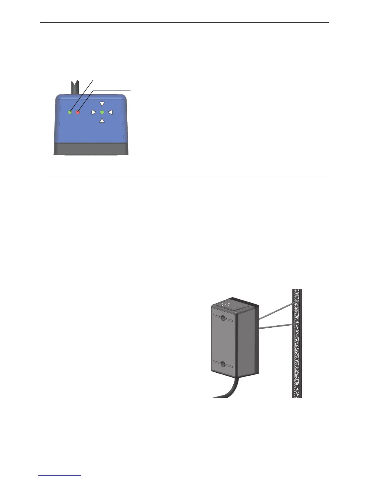
6.3.2 Power and status LED
Plug the RJ45 connector of the APS system into the downstream processing unit. The installer must follow the system
integrator‘s installation instructions as the correct installation is part of the system's safety (depending on system
integration, it can be SIL 3 level).
Details for the electrical connection are described in the APS Safety Manual.
The green and red LEDs located to the left (refer to
Figure 38) indicate the status of the APS.
• The green PWR LED indicates if the supply voltage for
the APS sensor is okay.
• The red STAT LED reports internal and communication
errors.
• For safety relevant operation, read the APS error and
APS status via the CAN / RS485 bus (for details refer
to the APS Safety Manual).
Figure 38: Power (PWR) and status (STAT) LED
6.3.3 APS alignment assistant
To be able to read the code tape, the APS system must be properly aligned. Two alignment aides help to position the
APS system:
•Alignmentspotlights
•Electronicalignmentassistant
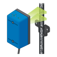
Alignment spotlights
The alignment spotlights are two red LED beams along
the optical axis of the APS sensor. They help to align the
APS sensor and the code tape.
The alignment spotlights can be activated by either:
• Powering up the sensor (while the code tape is not
in view of the cameras).
The alignment spotlights deactivate 5 min after first
recognizing the code tape.
• Waving a clean sheet of paper in front of the
cameras:
Do not use hand gestures as these may smudge the
optics of the APS sensor or the code tape.
Figure 39: Alignment spotlights in use
PWR LED (green)
STAT LED (red)
LED Color Function OFF ON Slow blinking (1 Hz) Fast blinking (5 Hz)
PWR Green Supply voltage No power Power OK - -
STAT Red Status signal No errors Reading error APS internal fault Communication error
Table 5: Power and status LED