18 © CEDES | V 2.2
Electronic alignment assistant
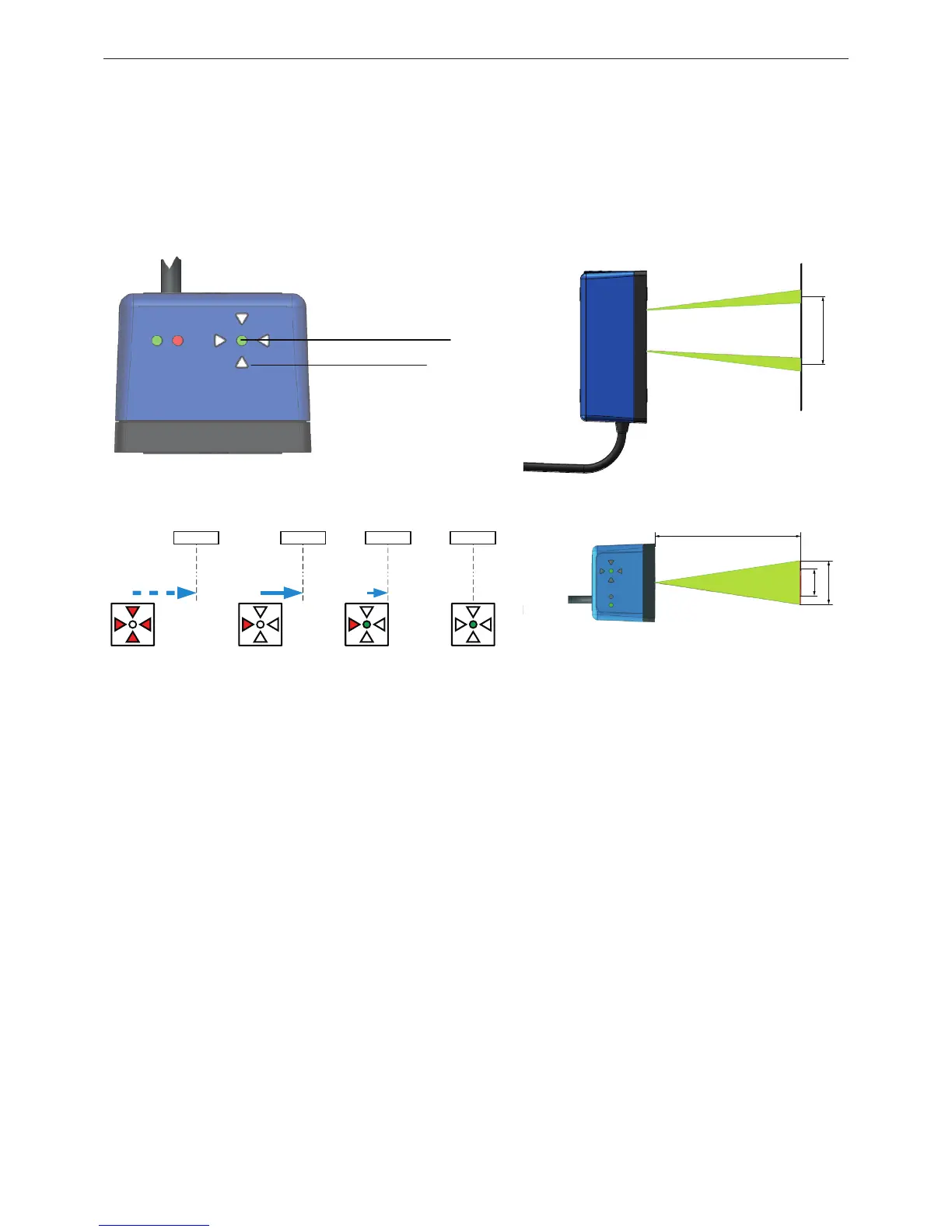
To fine-tune the APS system’s alignment, use the electronic alignment assistant. Four red directional LEDs (triangular
in shape) and one green center LED (circular) indicate the exact APS sensor reading position compared to the vertical
centre line of the code tape.
• The electronic alignment assistant is automatically activated as soon as the APS sensor is supplied with power and
can partially read the code tape.
• The four triangles pointing to the centre are the direction indicator for the sensor‘s movement to the optimal
adjustment. Move the sensor in the direction indicated by the triangular head for better alignment.
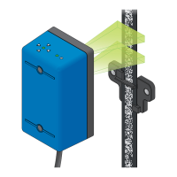
Figure 40: Indicator of the electronic alignment assistant
Figure 41: Interpretation of the electronic alignment assistant
Figure 42: Field of view of the cameras
4 × Alignment LED
POS STAT LED (green)
65 ±519
30
105 ±10
105 ±15
19
40
Code tape not visible Move right Move slightly right Position OK
Tape
Tape Tape Tape