ENGLISH
29
Installation and control elements
• CEDIMA
®
• Technical Documentation • All rights reserved as per ISO 16016 • Subject to modications due to progressive development •
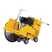
Blade guard xing screws on the joint cutter’s right side
Fig. 4.26
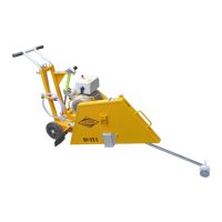
Blade guard and splash guard mounted from the machine’s right
side Fig. 4.27
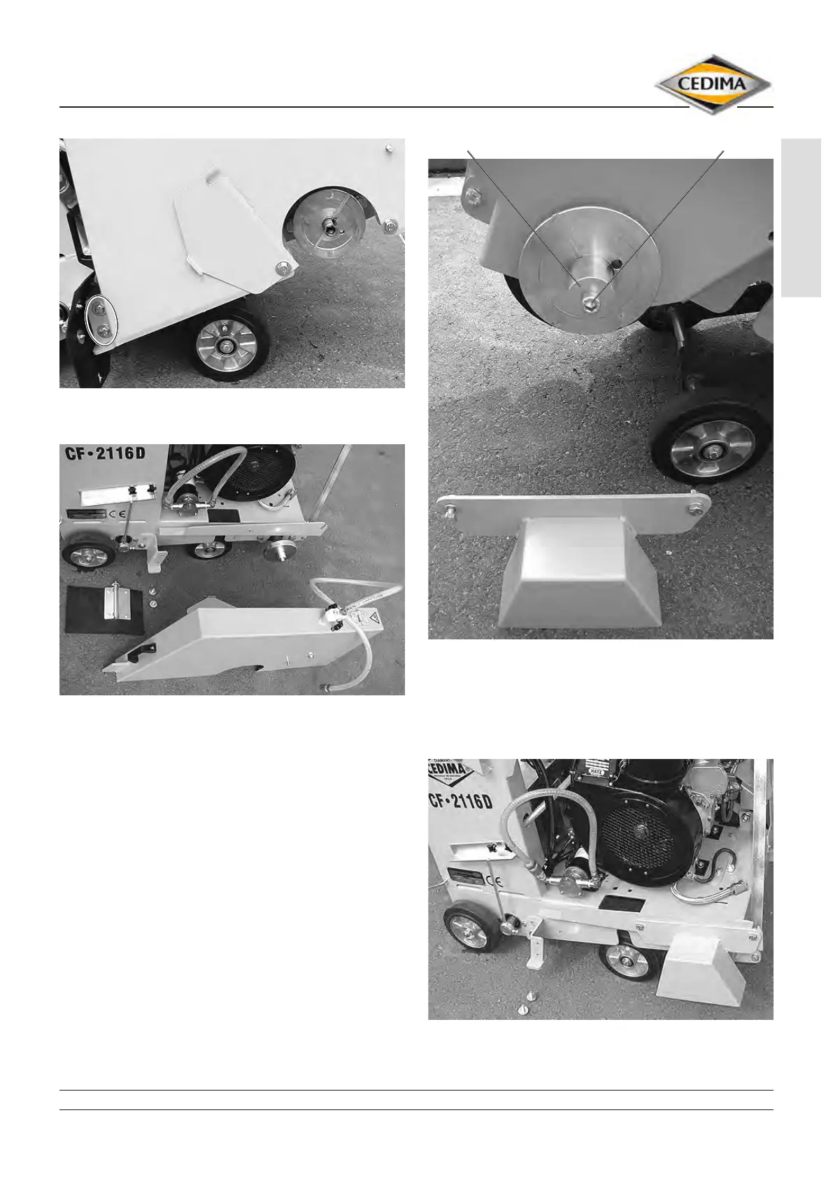
7. Dismount the cover of the blade mounting ange by
loosening and removing the two xing screws (with
washers) (g. 4.28).
8. Loosen and remove the cutting shaft screw and
dismount the mounting piece from the freely rotating
cutting shaft side (here: left side) (g. 4.28).
9. Mount the mounting piece (with cutting shaft screw)
on the now freely rotating cutting shaft side (here:
right).
Cover of blade mounting ange dismounted from the machine’s
left side Fig. 4.28
mounting piece cutting shaft screw
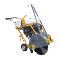
10. Mount the cover of the blade mounting ange with
the two xing screws (washers) on the now freely
rotating cutting shaft side (here: right, g. 4.29).
Cover of blade mounting ange mounted on the CF-2116 D’s
right side Fig. 4.29