ENGLISH
30
Installation and control elements
• CEDIMA
®
• Technical Documentation • All rights reserved as per ISO 16016 • Subject to modications due to progressive development •
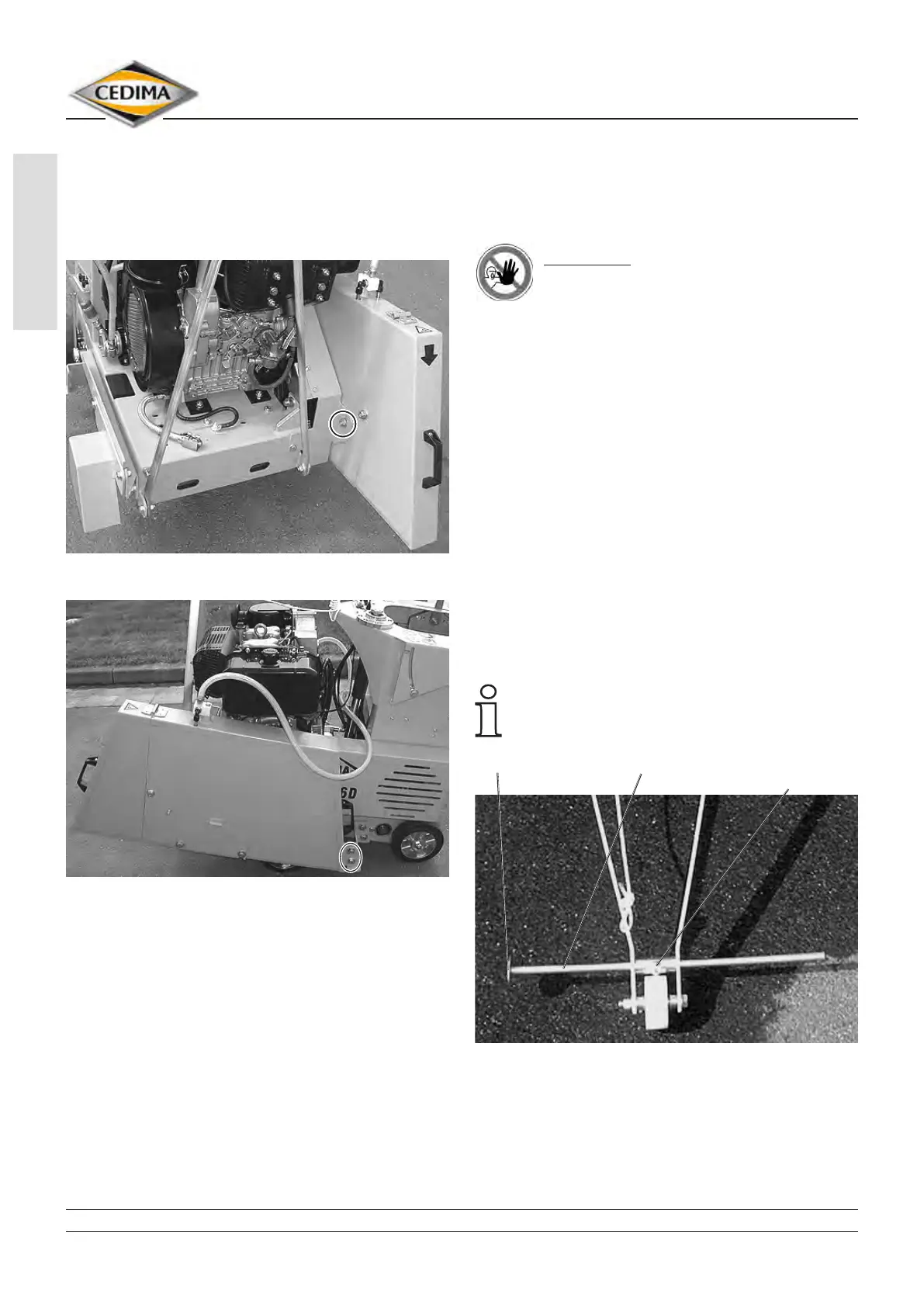
11. Lift the blade guard over the left cutting shaft side.
Screw the nut (with washer) at the fore inner side of
the blade guard (g. 4.30) and screw the two xing
screws (with washers) to the blade guard (rear, g.
4.31).
Blade guard mounted on the CF-2116 D’s left side Fig. 4.30
Blade guard mounted on the CF-2116 D’s left side Fig. 4.31
12. Connect the cooling water hose for the blade guard
to the water pumped (pumped water) or to the water
tank (water supplied under pressure, refer to section
4.7).
13. Mount the diamond saw blade (refer to section
4.5.3).
4.6 The pointers of the CF-2116 D
The front and rear pointers (g. 4.32 and 4.33) of the
CF-2116 D enable the operator to cut precisely along a
marked line in order to achieve a correct cutting line.
DANGER!
Danger of injury! The visors must only be
adjusted when the joint cutter has been
shut down and the saw blade does not rotate.
Adjust the pointers as follows:
1. Mount the diamond saw blade and lower it onto to
ground to be cut (onto the marked line).
2. Open the blade guard ap.
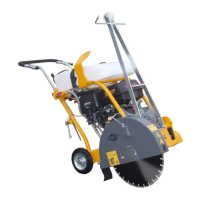
3. Lower the front pointer.
4. Align the joint cutter precisely with the saw blade
along a stretched cord, a rod or something similar to
the marked line (g. 4.34 and 4.35).
5. Loosen the counter nut and the clamping screw of
the front pointer rod and align the front pointer to the
marked line (cord) (g. 4.32, 4.34 and 4.35).
6. Re-tighten the counter nut and the clamping screw of
the front pointer.
7. Loosen the counter nut and the clamping screw
of the rear pointer and align the rear pointer to the
marked line (cord) (g. 4.33, 4.34 and 4.35).
Front and rear pointers can be interchanged for
right or left side cutting.
CF-2116 D, front pointer Fig. 4.32
front pointer pointer rod clamping screw
and counter nut