ENGLISH
33
Installation and control elements
• CEDIMA
®
• Technical Documentation • All rights reserved as per ISO 16016 • Subject to modications due to progressive development •
4. Lead the siphon hose ② from the water pump back-
wards beyond the water tank cantilever (g. 4.38 and
4.36).
5. Place the empty water tank upright on the water tank
cantilever and connect the siphon hose
② of the
water pump with the ball valve (Gardena coupling,
g. 4.38 and 4.39).
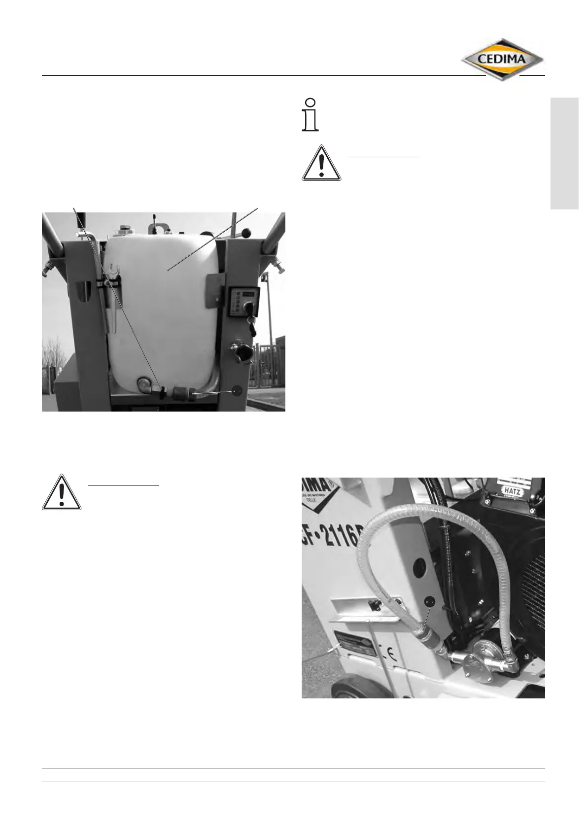
CF-2116 D, siphon hose ② connected to ball valve Fig. 4.40
ball valve water tank
➋
6. Open the water tank’s screw closure and ll in ap-
prox. 35 l cooling/rinsing water. Close the water tank.
ATTENTION!
Completely lled, the water tank’s weight
exceeds 25 kg and must therefore be
transported, according to the Employer’s Liability
Insurance Association, only with the help of lifting
devices.
7. Open the ball valve at the water tank (g. 4.40) and
switch ON the water pump (g. 4.9), after having
started the motor, before cutting.
4.7.2 Connecting water
supplied under pressure
When operating with water supplied under pressure
the cooling and rinsing water is delivered directly from
an external water hose via a dirt collector (lter) to the
blade guard hose (saw blade). The electrical water
pump is by-passed and remains shut off, the ball valve
of the water tank is disconnected and closed.
When operating with water supplied under
pressure the lled water tank can remain on the
CF-2116 D for vibration absorption.
ATTENTION!
Do not operate the water pump when
working with water supplied under
pressure.
Prepare the CF-2116 D for the operation with water
supplied under pressure as follows:
1. Close the water tank ball valve and disconnect the
siphon hose
② from the water tank ball valve (Gar-
dena coupling, g. 4.40 and 4.36).
2. Remove the empty water tank vertically from the CF-
2116 D.
3. Disconnect the blade guard hose
① from the water
pump connection (g. 4.38).
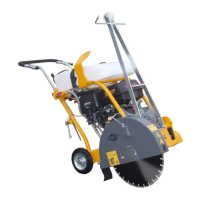
4. Pull the siphon hose
② forward for the water pump
and connect it to the water pump (g. 4.38 and 4.41).
5. Lead the blade guard hose
① backward and connect
it to the Gardena-coupling for water supplied under
pressure (g. 4.39, 4.42 and 4.43).
6. Connect the external water hose to the ball valve
(Geka-coupling) of the joint cutter’s connection for
water supplied under pressure and open the ball
valve (g. 4.43).
By means of the ball valve you regulate the water
supply to the diamond saw blade.
CF-2116 D, siphon hose ② connected to water pump connection
Fig. 4.41
➋