Maintenance of the system
______________________________________________________________________________________
NewTom VGi evo – Service Manual rev 6 9-14
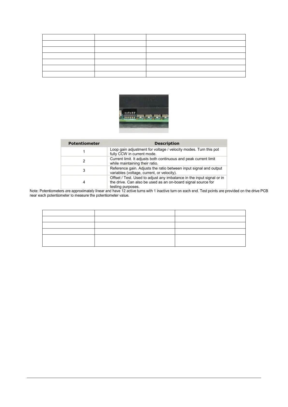
2. Set the potentiometers as following:
COMPLETELY COUNTER-CLOCKWISE
COMPLETELY COUNTER-CLOCKWISE
COMPLETELY COUNTER-CLOCKWISE +
6 ROTATIONS CLOCKWISE
3. Connect Voltage DC Tester probes on P2 connector (Power Connector) as following
Red Pin P2 Connector Pin B (2)
Black Pin P2 Connector Pin A (1)
Moving the column in UP direction by the consolle. Wait a few seconds so that the speed is maximum (2nd
gear)
Set the Potentiometer n. 3 until the voltage is about 36Vdc ± 0.5V
Moving the column in DOWN direction by the console. Wait a few seconds so that the speed is maximum (2nd
gear)
Set the Potentiometer n. 4 until the measured voltage are as similar as possible to the value obtained in the
direction UP (obviously with reverse polarity: approx -36Vdc ± 0.5V)
4. Moving the column in UP direction by the console. Wait a few seconds so that the speed is maximum (2nd
gear) and verify that the voltage is still within the predetermined range 36Vdc ± 0.5V.
If not, set again the Potentiometer n. 3
 Loading...