www.cellarcool.com | Page 43
Magnum Series
If you will install the unit on the ground or on a concrete mounting platform, do the following:
1. Mark the positions for four expansion bolt based on dimensions in the Unit Mounting Dimensions chart.
2. Pre-drill holes for expansion bolts.
3. Clean concrete dust away from holes.
4. Place a nut on the end of each expansion bolt.
5. Hammer expansion bolts into the pre-drilled holes.
6. Remove the nuts from expansion bolts, and place outdoor unit on bolts.
7. Put washer on each expansion bolt, then replace the nuts.
8. Using a wrench, tighten each nut until snug.
If you will install the unit on a wall-mounted bracket , do the following:
1. Mark the position of bracket holes based on dimensions in the Unit Mounting Dimension chart.
2. Pre-drill the holes for the expansion bolts.
3. Clean dust and debris away from holes.
4. Place a washer and nut on the end of eachexpansion bolt.
5. Thread expansion bolts through holes in mounting brackets, put mounting brackets in position, and hammer expan-
sion bolts into the wall.
6. Check that the mounting brackets are level.
7. Carefully lift unit and place its mounting feet on brackets.
8. Bolt the unit rmly to the brackets.
1. Using a crescent wrench, grip the body of the valve. Do not grip the nut that seals the service valve.
2. While rmly gripping the body of the valves, use a torque wrench to tighten the are nut according to the correct
torque values.
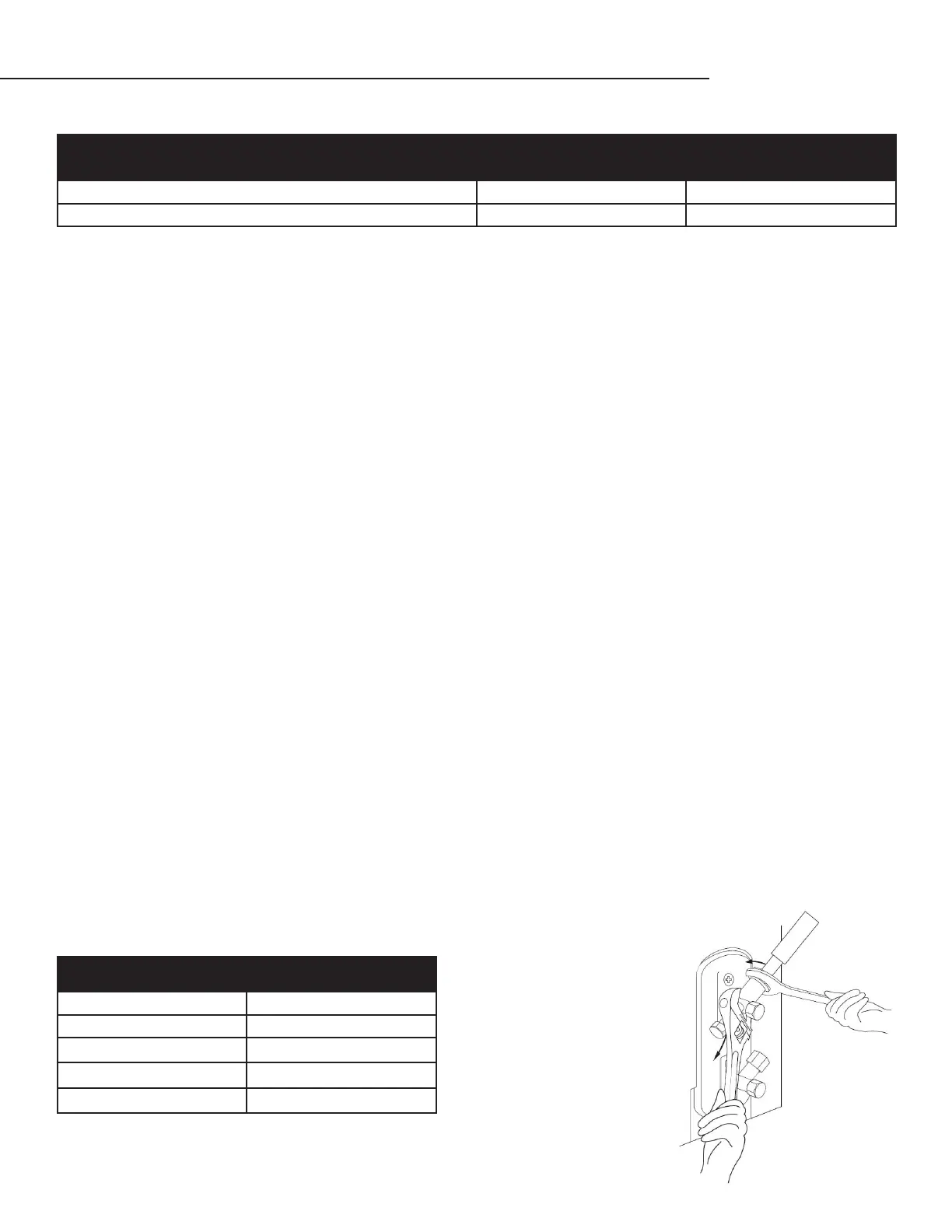
The outside unit’s terminal block is protected by an electrical wiring cover on the side of the unit. Remove the cover and wire
according to diagram above and visual instructions below.
4. Connect line set to condensing unit
Line set piping size is determined by the unit size and the line set length. Determine the length before selecting the size. For
the vertical rise on the suction and liquid lines refer to the line set piping examples previously shown. When the condens-
ing unit is mounted above the evaporator unit it is recommeded that the suction line should have oil saving bends placed
every 15’.
TORQUE REQUIREMENTS
INSTALLING THE CONDENSING UNIT, CONTINUED
Outdoor Unit Dimensions (in.)
Mounting Dimensions
Distnace A (in.) Distance B (in.)
18000: 31.18”L x 10.75”W x 23.25”H 19.72” 10.71”
24000: 35.25”L x 12”W x 33.7”H 19.72” 10.71”
Outer Diameter of Pipe (in.) Tightening Torque (lb/ft)
¼” 11 lb/ft
¼” 18.4 lb/ft
½” 25.8 lb/ft
⁄” 33.19 lb/ft
¾” 47.94 lb/ft