Page 44
TWIN MG 092223
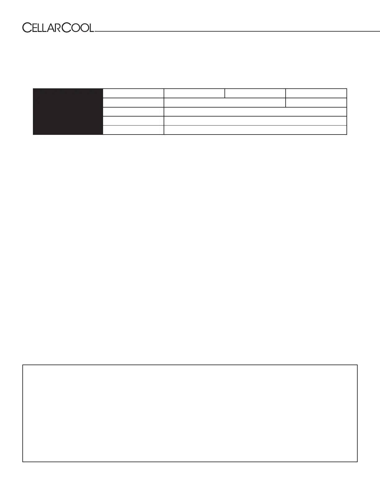
LINE SET PIPING SIZE
Liquid Line King Valve
This location is used to charge the system with liquid refrigerant and identify the high side pressure of the system.
Calculating Subcooling
To determine the subcooling of the system, calculate the dierence between the high side pressure of the system
(converted to temperature) and the temperature of the liquid line. The temperature of the liquid line will be taken on
the exterior of the condensing unit, about 4” away from the housing. *Saturation temp — liquid line temp.
5-15°F SUBCOOLING REQUIRED FOR WARRANTY APPROVAL
5. Pressure Test
After the line set has been connected securely to the evaporator and condensing unit, remove valve stem caps from low-
pressure (suction) and high-pressure (liquid) valves on condensing unit. Ensure service valve stems are in the back-seated
position. If valve cores have been removed, they should be reinstalled in valves after pressure testing, vacuum, and charging
procedures are complete.
Connect charge hoses of the manifold gauge to the service ports on the outdoor unit’s low pressure and high pressure valves.
Leave gauge manifold knobs in closed position until nitrogen is ready to be admitted into the system. Connect service hose
from service port on manifold to nitrogen regulator. Set nitrogen tank regulator to approximately 225 psi. Open both high
side and low side gauge manifold knobs SLOWLY at the same time to admit nitrogen into the system until the gauge manifold
reads 225 psi, then close gauge manifold knobs. Let pressure stand for minimum of 10 minutes. Use soapy solution to check
are connection points for leaks. If no leaks are present and pressure is maintained after 10 minutes of pressure test, proceed
with evacuation process. If any leak is detected, it must be corrected before moving onto the evacuation process.
6. Air Evacuation/ Vacuum
1. Remove the nitrogen from the system
2. Remove the nitrogen tank from the manifold and attach the manifold to the vacuum pump
3. Install service caps on the valves.
4. After conrming that there is fresh oil in the vacuum pump, connect the hose from the manifold to the
pump.
5. Start the pump and run it until micron gauge reads 250 microns or less.
6. Once vacuum of 250 microns or less is achieved, disconnect the vacuum pump from the system.
7. Remove the micron gauge from the access valve.
8. Close the valves on the manifold.
NOTE: For adjusting the service valves on the condensing unit a 3/16” allen wrench is needed.
INSTALLING THE CONDENSING UNIT, CONTINUED
3. Loosen the aring nut slightly, then tighter again.
4. Repeat steps for the remaining pipe.
Magnum 18000/24000 Line Set Length <25 ft. 26-50 ft. 50-100 ft.
Suction Line
Horizontal Tubing ⁄” ¾”
Veritcal Rise ⁄”
Liquid Line
Horizontal Tubing ⁄”
Vertical Rise ⁄”