www.cellarcool.com | Page 45
Magnum Series
INSTALLING THE CONDENSING UNIT, CONTINUED
7. Charging
The chart below provides the approximate refrigerant charge amount for initial startup based on the line set
length. Please see the chart below for the initial charge amount. The installing technician may still need to add ad-
ditional charge and dial in the desired subcooling to achieve optimum performance.
Subcooling range is between 5-15°F:
• When charging during colder ambient temperatures (below 60°F), your target will be the lower end of the
subcooling range.
• When charging during hotter ambient temperatures (above 95°F), the target will be the upper end of the
subcooling range.
1. Invert refrigerant tank on a scale. Purge the charging hose up to the manifold and then zero out the scale in
preparation for liquid refrigerant charging.
2. With the power o to the condensing unit, admit liquid refrigerant through the liquid line service valve.
3. Prior to turning on condensing unit, ensure evaporator (air handler) unit is ON and controller is calling for
cooling.
4. Turn on the circuit breaker for the condensing unit. The compressor and condenser fan should begin to
operate.
5. After startup, wait a minimum of 10 minutes for system to stabilize before checking subcooling or super-
heat.
6. Place refrigerant tank in upright position in preparation for adding vapor refrigerant (if necessary).
7. Add refrigerant (in vapor form) to the low side of the system through the suction line service port if neces-
sary to achieve recommended subcooling.
8. Check the superheat at suction service valve on the condensing unit.
9. Adjust the TXV until the superheat is between 10-25°F at the service valve.
10. After recommended superheat and subcooling is achieved, place the service valve stems in the back-seat
position (all the way out counter-clockwise) and reinstall the Schrader valve cores. Once hoses are disnect-
ed, reinstall all caps on service valves.
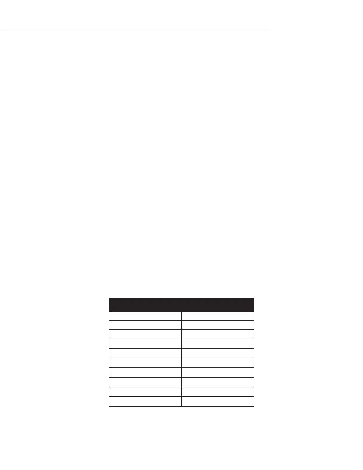
APPROXIMATE INITIAL CHARGE CHART
Line Set Charge Total
10’ Line Set 4.62 lbs
20’ Line Set 5.00 lbs
30’ Line Set 5.37 lbs
40’ Line Set 5.75 lbs
50’ Line Set 6.12 lbs
60’ Line Set 6.50 lbs
70’ Line Set 6.87 lbs
80’ Line Set 7.25 lbs
90’ Line Set 7.62 lbs
100’ Line Set 8.00 lbs