EAGLE CONTROLLER – INSTALLATION & COMMISSIONING INSTRUCTIONS
EN1Z-0970GE51 R0918 20
Table 15. Specifications of AOs
criteria value
output type
0…10 V (default)
2…10 V
max. output range 0 … 11 VDC (1 mA)
min. resolution 8 bit
min. accuracy ± 150 mV
max. wire length 400 m
wire cross section See Table 9 on pg. 14.
protection against short-circuiting, 24 VAC
Binary Inputs / Pulse Counters
Both the CLEA2026Bxx and the CLEA2014Bxx are equipped
with four binary inputs (static dry-contact inputs) / pulse
counters (fast totalizers).
Table 16. Specifications of BIs
criteria value
input type
binary input (static dry-contact)
pulse counter (fast totalizer)
current rating
(closed input)
2 mA
open contact
voltage
24 VDC
protection against short-circuiting, 24 VAC
Binary Input Specifications
The binary inputs of the EAGLE are static dry-contact inputs.
This reduces the wiring effort, as it is then not necessary to
distribute an auxiliary voltage signal.
open contact ≥ 3000 Ω (24 VDC on BI terminal)
closed contact ≤ 500 Ω (short-circuit current: 2.0 mA)
The polarity (normal = N.O. contact or reverse = N.C. contact)
configuration defines if a logical 1 or a logical 0 is detected for
a closed contact. This is done by selecting (in CARE) one of
the following options:
normal (default)
closed external contact → state=1
open external contact → state=0
reverse
closed external contact → state=0
open external contact → state=1
Pulse Counter Specifications
Using CARE, the binary inputs of the EAGLE can be con-
figured as pulse counters (fast totalizers) for operation in
conjunction with devices equipped with an open collector
output.
If the duty cycle is 50% / 50%, the pulse counter supports up
to 15 Hz. Counting is done on the rising edge.
Table 17. BIs of EAGLE configured as fast totalizers
frequency
max. 15 Hz
pulse ON
min. 25 ms
pulse OFF
min. 25 ms
bounce
max. 5 ms
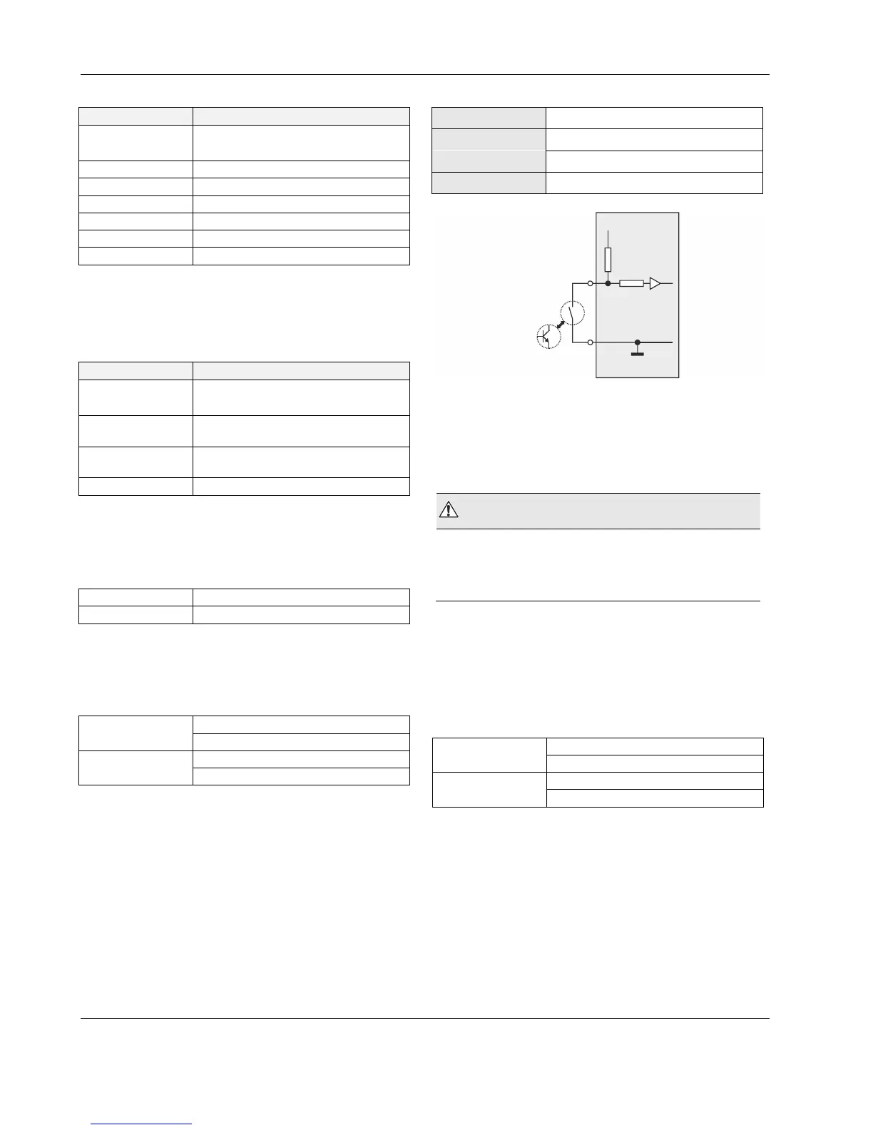
COM
FAST
TOTALIZER
DRY CONTACT
24 VDC =
0 V =
BI
24V
open
closed
GND
Fig. 32. Internal wiring of BI
Binary Outputs
The EAGLE features eight (CLEA2026Bxx) or four
(CLEA2014Bxx) binary outputs arranged in two blocks
(BO1…4 and BO5..8, respectively).
WARNING
Risk of electric shock or equipment damage!
Low voltage and line voltage must not be wired within
the same block.
In the event of an application stop (e.g., during application
download), the binary outputs assume the safety positions
configured in CARE.
The polarity (normal = N.O. contact or reverse = N.C. contact)
configuration defines if a relay is open or closed, depending
upon whether there is a logical 1 or a logical 0. This is done
by selecting (in CARE) one of the following options:
normal (default)
state=1 → relay contact is closed
state=0 → relay contact is opened
reverse
state=0 → relay contact is closed
state=1 → relay contact is opened