EAGLE CONTROLLER – INSTALLATION & COMMISSIONING INSTRUCTIONS
31 EN1Z-0970GE51 R0918
MODBUS CONNECTION
The EAGLE controller supports Modbus RTU Master functionality.
Modbus slaves can be connected to either of the two onboard RS485 interfaces (but not to both simultaneously): RS485-1
(consisting of push-in terminals 24 [GND-1], 25, and 26) or RS485-2 (consisting of push-in terminals 29, 30, 31 [GND-2]).
NOTE: GND-2 is internally connected with 24V-0 (terminal 1) and system GND (terminals 19+37)
Modbus Considerations
RS485-1 (isolated)
˗ Max. Modbus length: 1200 meters (9.6 – 76.8 kbps) or 1000 meters (115.2 kbps) (see also section "RS485 Standard" on
pg 9).
˗ Use only shielded, twisted-pair cable and daisy-chain topology.
˗ Must conform to EIA-RS485 cabling guidelines.
RS485-2 (non-isolated)
˗ Max. Modbus length: 1200 meters (9.6 – 76.8 kbps) or 1000 meters (115.2 kbps) (see also section "RS485 Standard" on
pg 9).
˗ Use only shielded, twisted-pair cable and daisy-chain topology.
˗ Ground noise should not exceed the EIA-485 common mode voltage limit.
˗ Must conform to EIA-RS485 cabling guidelines.
˗ Should not extend beyond a single building.
Max. no of Modbus devices per EAGLE: 32 (including the EAGLE, itself, which is counted twice)
Connecting RS485-1 to the Modbus
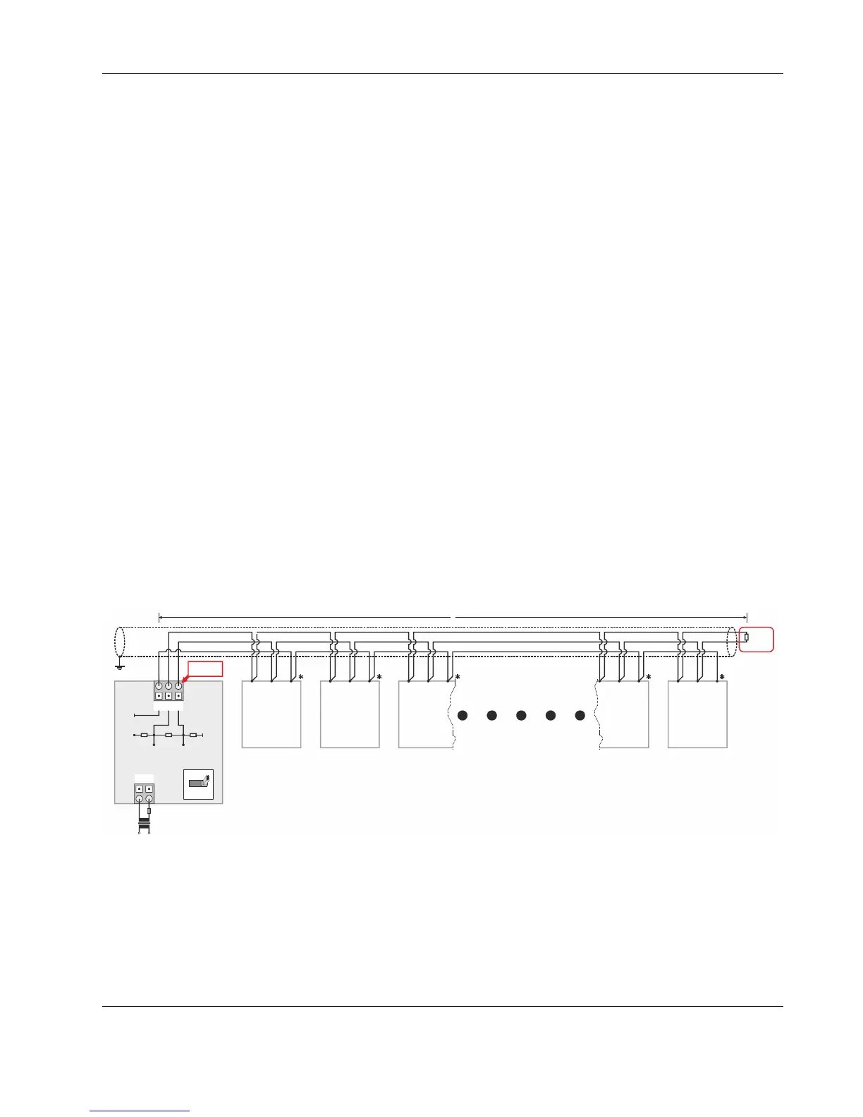
With regards to Fig. 47, please note the following:
NOTE: Always power each EAGLE and the connected Modbus slaves via separate transformers.
NOTE: For "L," see section "RS485 Standard" on pg. 9.
NOTE: If any of the devices are electrically isolated, it is recommended that those devices be connected to signal ground.
See section "RS485 Standard" on pg. 9.
Example: EAGLE Modbus Master Controller and Connected Modbus RTU Slaves (with inserted termination
resistor)
1 2
24V~
24~0
242526
F1
230 V
24 V
L
GND-1
GND-1
+5V
ISO
RS485-1 (+) RS485-1 (-)
550 OHM 150 OHM 550 OHM
RS485 +
RS485 -
GND
RS485 +
RS485 +
RS485 +
RS485 -
RS485 -
GND
GND
GND
R
T
RS485 -
RS485 +
RS485 -
GND
EAGLE
*CONNECT GND, IF AVAILABLE.
Modbus
Slave #1
Modbus
Slave #2
Modbus
Slave #3
Modbus
Slave #N-1
Modbus
Slave #N
120 Ohm
RS485-1
Modbus
Module
END
END
BIAS
MID
Fig. 47. Connection of EAGLE Modbus Master Controller to Modbus RTU slaves via RS485-1
The termination resistor must be inserted directly into the terminals of the last Modbus RTU slave.