EAGLE CONTROLLER – INSTALLATION & COMMISSIONING INSTRUCTIONS
EN1Z-0970GE51 R0918 6
Bus and Port Connections
Overview
WARNING
Risk of electric shock or equipment damage!
► Do not touch any live parts in the cabinet!
► Disconnect the power supply before making connections
to or removing connections from terminals of the EAGLE
Controller or Panel Bus I/O modules.
► Do not reconnect the power supply until you have
completed installation.
► Due to the risk of short-circuiting (see Fig. 23), it is
strongly recommended that the EAGLE controller be
supplied with power from a dedicated transformer.
However, if the EAGLE controller is to be supplied by the
same transformer powering other controllers or devices
(e.g., the PW M-Bus Adapter), care must be taken to
ensure that correct polarity is observed.
► Observe the rules regarding electrostatic discharge.
BI1
BI2
BI3
BI4
GND
UI1
UI2
UI3
UI4
UI5
UI6
UI7
24 25 26 27 28 29 30 31 32 33 34 35 36 37 38 39 40 41 42 43 44 45 46
UI8
47
DO1
DO2
DO3
IN
IN4
DO4
DO5
IN5
IN6
DO6
DO7
IN7
IN8
DO8
GND
AO1
AO2
AO3
5
6 7 8 9 10 1112131415161718 19202122
24V-0
24V~
1
AO4
23
6 7
4
5
GND1
485-1+
485-1-
GND2
485-2+
485-2-
UI9
UI10
2
RS232
RS485-1
END
BIAS
MID
1
8
2
3
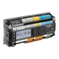
Fig. 2. Models with built-in HMI (top view)
BI1
BI2
BI3
BI4
GND
UI1
UI2
UI3
UI4
UI5
UI6
UI7
24 25 26 27 28 29 30 31 32 33 34 35 36 37 38 39 40 41 42 43 44 45 46
UI8
47
DO1
DO2
DO3
IN
IN4
DO4
DO5
IN5
IN6
DO6
DO7
IN7
IN8
DO8
GND
AO1
AO2
AO3
5678910
11 12
13
14
15 16
17
18 19 20
21 22
24V-0
24V~
1
AO4
23
6 7
4
5
GND1
485-1+
485-1-
GND2
485-2+
485-2-
UI9
UI10
2
9
J1 J8
RS232
RS485-1
END
BIAS
MID
1
8
2
3
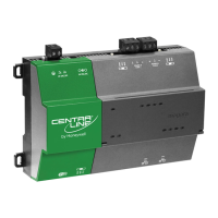
Fig. 3. Models without built-in HMI (top view)
1
8
3
J1 J8
2
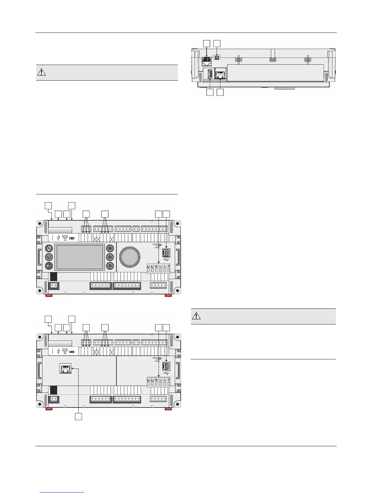
Fig. 4. All models (side view)
Legend
1 RS232 / RJ45 socket (for M-Bus connection and
factory debugging)
2 USB 2.0 Host Interface (for connection to IF-LON)
3 Ethernet / RJ45 socket (for BACnet IP communication)
– all models except CLEA2014B21 and CLEA2014B31
4 RS485-1* (isolated; for BACnet MS/TP, Panel Bus, or
Modbus RTU Master communication)
5 RS485-2* (non-isolated; for BACnet MS/TP, Panel
Bus, or Modbus RTU Master communication)
6 LEDs
7 USB 2.0 Device Interface (for connection to CARE /
XW-Online and web browsers, CL-Touch, or other 3
rd
-
party touch panels)
8 Three-position slide switch (for setting bias and ter-
mination resistance of RS485-1)
9 RJ45 socket for connection of CLEAHMI21 External
HMI – CLEA2000B31, CLEA2014B31, CLEA2014B32,
CLEA2026B31, only
* Modbus RTU Master communication is possible on either
one of the two RS485 interfaces, but not on both of them
concurrently.
NOTE: In the case of the CLEA2014B21 and
CLEA2014B31, at least one of the two RS485
interfaces must be assigned to BACnet MS/TP.
The other RS485 interface can then be assigned to
either Panel Bus, Modbus, or BACnet MS/TP.
WARNING
Risk of electric shock or equipment damage!
► It is prohibited to connect any of the RJ45 sockets of the
EAGLE Controller to a so-called PoE-enabled device
("Power over Ethernet").